Low voltage differential signal (LVDS) transmitter with output power control

a low voltage differential and output power control technology, applied in the field ofdifferential signal interfaces, can solve the problems of limiting output voltage and reducing supply current to output driver circuitry

Active Publication Date: 2010-05-18
NAT SEMICON CORP
View PDF2 Cites 12 Cited by
  • Summary
  • Abstract
  • Description
  • Claims
  • Application Information

AI Technical Summary

Problems solved by technology

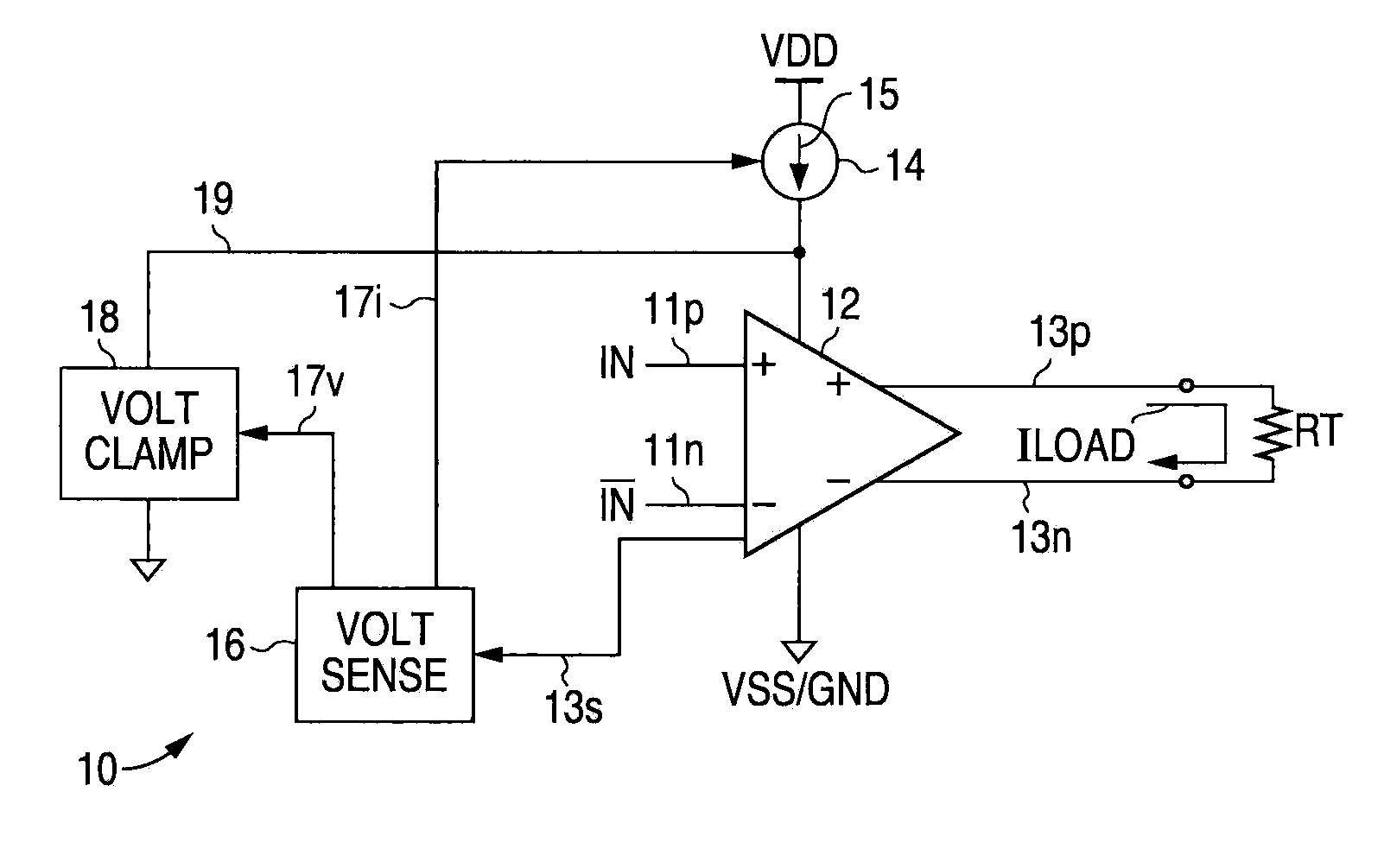
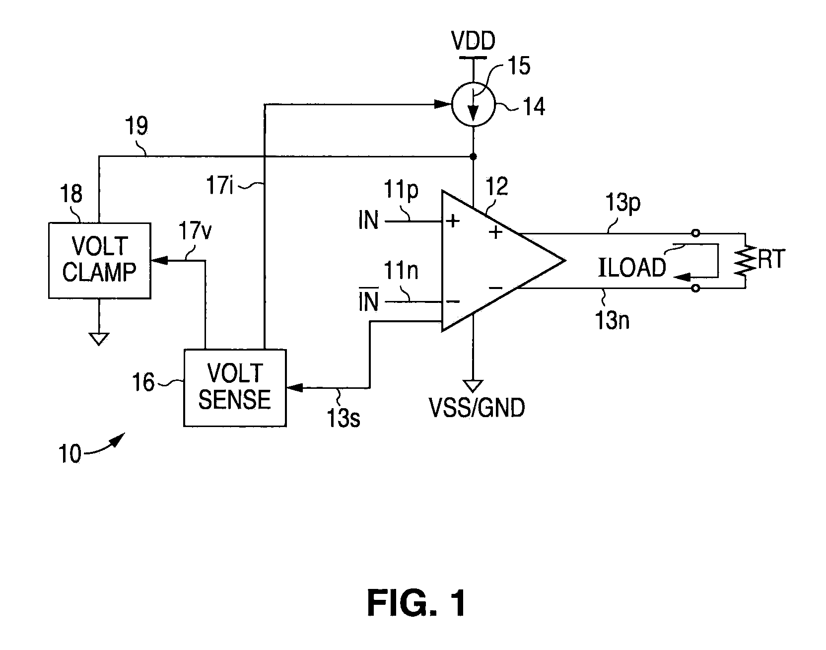
When a proper termination impedance is not connected to the output, the resulting improper output current flow (e.g., zero output current when no termination impedance is connected) is detected by the sensing circuitry, which causes the supply current to the output driver circuitry to be reduced.
Additionally, further in response to such detection of improper output current flow, the sensing circuitry can cause the output voltage to be limited, e.g., clamped, at a predetermined maximum magnitude.

Method used


Image

  • Low voltage differential signal (LVDS) transmitter with output power control
  • Low voltage differential signal (LVDS) transmitter with output power control
  • Low voltage differential signal (LVDS) transmitter with output power control

Examples


Embodiment Construction

[0030]The following detailed description is of example embodiments of the presently claimed invention with references to the accompanying drawings. Such description is intended to be illustrative and not limiting with respect to the scope of the present invention. Such embodiments are described in sufficient detail to enable one of ordinary skill in the art to practice the subject invention, and it will be understood that other embodiments may be practiced with some variations without departing from the spirit or scope of the subject invention.

[0031]Throughout the present disclosure, absent a clear indication to the contrary from the context, it will be understood that individual circuit elements as described may be singular or plural in number. For example, the terms “circuit” and “circuitry” may include either a single component or a plurality of components, which are either active and / or passive and are connected or otherwise coupled together (e.g., as one or more integrated circ...


PUM


Abstract

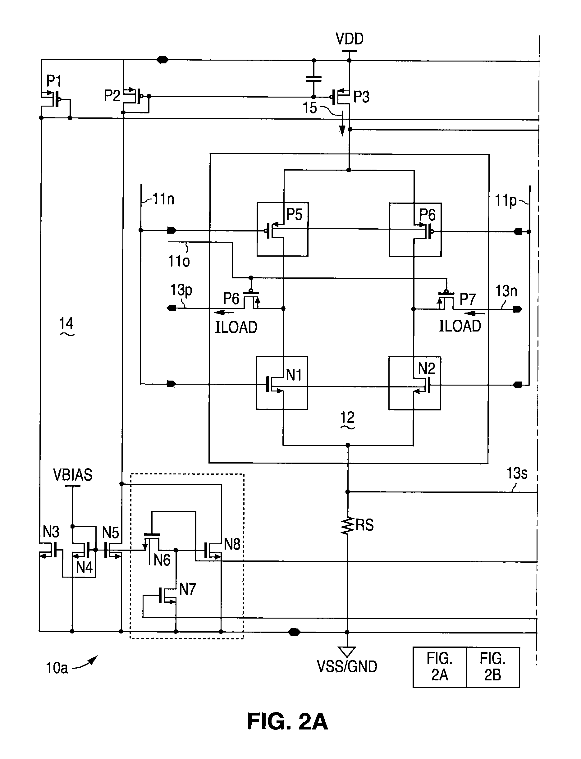
A low voltage differential signal (LVDS) transmitter with output power control. Internal sensing circuitry monitors output current flow through the termination impedance. When a proper termination impedance is not connected to the output, the resulting improper output current flow (e.g., zero output current when no termination impedance is connected) is detected by the sensing circuitry, which causes the supply current to the output driver circuitry to be reduced. Additionally, further in response to such detection of improper output current flow, the sensing circuitry can cause the output voltage to be limited, e.g., clamped, at a predetermined maximum magnitude.

Description

BACKGROUND[0001]1. Field of the Invention[0002]The present invention relates to differential signal interfaces, and in particular, to low voltage differential signal (LVDS) transmitters for operating with reduced power dissipation.[0003]2. Related Art[0004]Differential input / output (I / O) signal interfaces are widely used for reliable high-speed data transfer in many forms of data communication channels. As is well known, differential signaling is preferred to single ended signaling due to its highly robust resistance to common mode noise associated with both conducted and radiated electromagnetic interference (EMI), as well as lower power dissipation compared to single ended static complementary metal oxide semiconductor (CMOS) implementations. Further, differential signaling generally also produces lower EMI emissions than their single ended counterparts due to reduced signal magnitudes and switching currents.[0005]However, notwithstanding the ability to deliver reliable signals wi...

Claims


Application Information

Patent Timeline
Patent Type & Authority Patents(United States)
IPC IPC(8): H03B1/00
CPCH03K19/018528
Inventor SNOWDON, KENNETH P.DUZEVIK, IVAN
Owner NAT SEMICON CORP
Why Eureka
Try Eureka