Method to provide a higher reference voltage at a lower power supply in flash memory devices

a flash memory device and reference voltage technology, applied in the field of electronic circuits, can solve the problems of increasing the difficulty of obtaining device speed requirements, insufficient gain-bandwidth product of the reference circuit, and inability to validate assumptions, etc., to achieve fast and stable reference voltage and rapidly stabilize the reference voltage. the effect of substantial stability

Active Publication Date: 2010-05-25
INFINEON TECH LLC
View PDF13 Cites 27 Cited by
  • Summary
  • Abstract
  • Description
  • Claims
  • Application Information

AI Technical Summary

Benefits of technology

[0008]In one embodiment, the fast voltage reference circuit further comprises a start-up circuit that initially discharges a potential at the bias supply and comparator circuits, then initializes a reference voltage generated at a reference node of the variable divider circuit at about zero volts in order to improve repeatability.
[0011]The comparator circuit is configured to compare the bias supply voltage to the reference voltage, and drive the bias supply via the active feedback path and the variable divider circuit in response to the comparison, thereby quickly stabilizing the reference voltage FVREF to a final level, thereby producing a stable, fast reference voltage signal FVREF that is substantially independent of supply voltage and process variations.
[0016]In one embodiment, a method of providing a fast and stable reference voltage, comprises: providing an impedance for a variable divider circuit, selecting a variable current reference for the variable divider circuit based on a desired reference voltage, translating the reference current through the impedance into the reference voltage, comparing the reference voltage to a bias supply voltage which varies as a function of feedback from a node of the variable divider circuit having a negative function of a supply voltage and substantially no function of temperature, and driving the differential voltage of the comparison into the variable divider circuit to rapidly stabilize the reference voltage substantially independent of variations in supply voltage and process variations.

Problems solved by technology

However, in many cases, this is not a valid assumption.
Under some of these conditions, the gain-bandwidth product of the reference circuit may be inadequate.
Further, as supply voltage levels decrease due to these higher density architectures, device speed requirements may be increasingly difficult to obtain, particularly at low supply voltage and reference levels, and at low operating currents over wide operating temperatures.
These issues are particularly evident during read operations at low power supply voltages (Vcc's) wherein the read margin decreases, resulting in an inaccurate read at low supply voltages.
The particular arrangement of bandgap voltage reference of FIG. 1, however, can not be used directly for the high speed circuits being considered, because of reduction in the gain-bandwidth product of the reference at higher speeds and low power supply voltages.

Method used


Image

  • Method to provide a higher reference voltage at a lower power supply in flash memory devices
  • Method to provide a higher reference voltage at a lower power supply in flash memory devices
  • Method to provide a higher reference voltage at a lower power supply in flash memory devices

Examples


Embodiment Construction

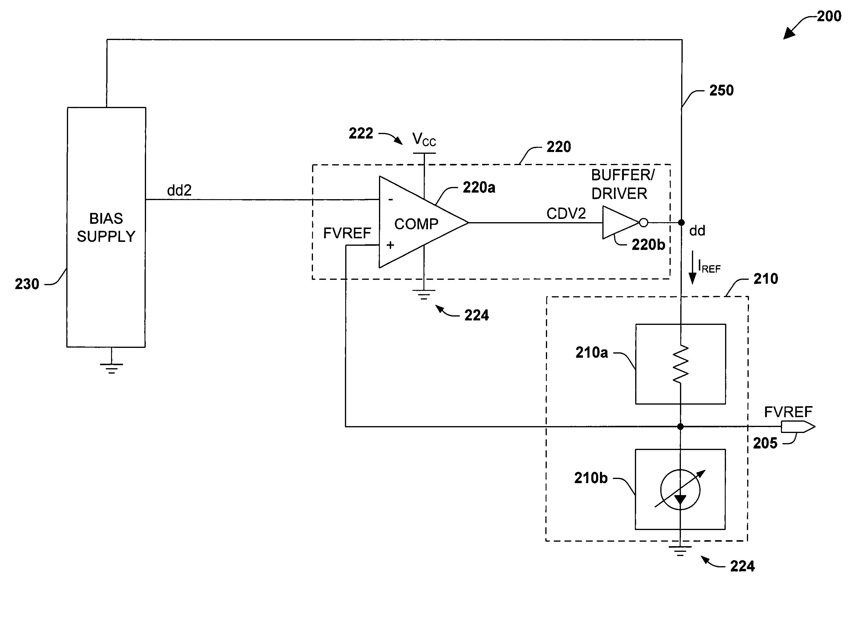
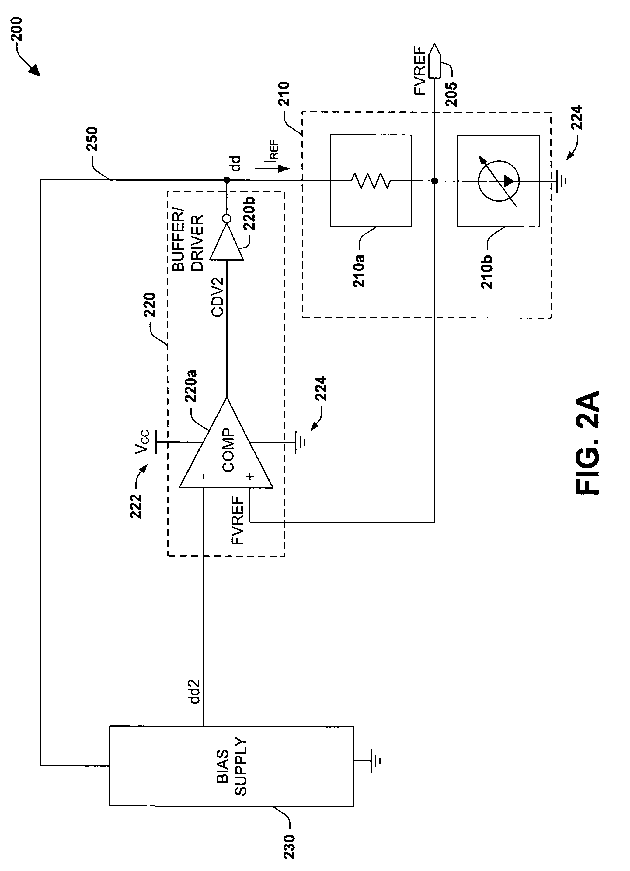
[0026]The present invention will now be described with reference to the drawings, wherein like reference numerals are used to refer to like elements throughout. The figures and the accompanying description of the figures are provided for illustrative purposes and do not limit the scope of the claims in any way. The present invention relates to an electronic circuit for producing a fast voltage or current reference which is substantially independent of supply voltage fluctuations, and which may be used, for example, to provide a fast reference voltage for a word line or a voltage booster for the read mode operations of memory cells. The invention comprises bias supply and comparator circuits, a variable divider circuit, and a feedback path between the variable divider circuit and the bias supply.

[0027]FIGS. 2A, 2B, and 2C illustrate system level functional block diagrams of exemplary fast voltage reference circuits 200, 201, and 202, respectively, in which various aspects of the inve...


PUM


Abstract

A fast reference circuit having active feedback includes a bias supply circuit and a variable divider circuit connected by an active feedback path to the bias supply circuit, and a comparator circuit connected to the variable divider circuit, the bias supply circuit, and a reference node of the variable divider circuit. In one embodiment, a start-up circuit initially discharges a potential at the bias supply and comparator circuits, then initializes a reference voltage at the reference node at about zero volts to improve repeatability. In one embodiment, the variable voltage divider comprises an impendence that is trimmed based on a sheet resistance of a process used to fabricate the fast reference circuit, and further comprises a variable reference current circuit coupled to the impedance and configured to generate a current having a value based on a desired reference voltage and to conduct the current through the impedance, thereby generating the reference voltage associated therewith. The comparator circuit is configured to compare the bias supply voltage to the reference voltage, and drive the bias supply and the variable divider circuit in response to the comparison, thereby quickly stabilizing the reference voltage.

Description

FIELD OF INVENTION[0001]This invention relates to electronic circuits and more particularly relates to voltage reference circuits for flash memory devices.BACKGROUND OF THE INVENTION[0002]Voltage and current reference circuits find many applications in electronic circuits including Flash and other types of electronic memory device applications. The bandgap reference circuit is a common circuit solution for supplying a voltage or current reference for such applications. FIG. 1 is a prior art bandgap circuit 100 and operates generally as follows. P1 and P2 act as a standard MOS current mirror providing current to Q1 and Q2, which are configured as a bipolar current mirror. Q1 and Q2 are sized differently; therefore, although they conduct the same current, they have different current densities. Therefore, there will be a difference in their Vbe voltages and the difference will be reflected in the current through R1. VREF is a voltage reference that is a function of the current through ...

Claims


Application Information

Patent Timeline
Patent Type & Authority Patents(United States)
IPC IPC(8): G05F1/575
CPCG05F3/08G11C16/30G11C5/147
Inventor YANG, TIEN-CHUNWU, YONGGANGYANG, NIAN
Owner INFINEON TECH LLC
Why Eureka
Try Eureka