Method of manufacturing stator unit, and motor using the stator
a stator unit and stator technology, applied in the direction of positive displacement liquid engines, magnets, piston pumps, etc., can solve the problems of difficult mechanization (automation) of the twining process of the wire, the diameter of the wire used for the small motor is so small, and the needle of the wire-winding machine cannot be easily placed therebetween, so as to facilitate the twining process and prevent the open circuit of the wire
- Summary
- Abstract
- Description
- Claims
- Application Information
AI Technical Summary
Benefits of technology
Problems solved by technology
Method used
Image
Examples
first preferred embodiment
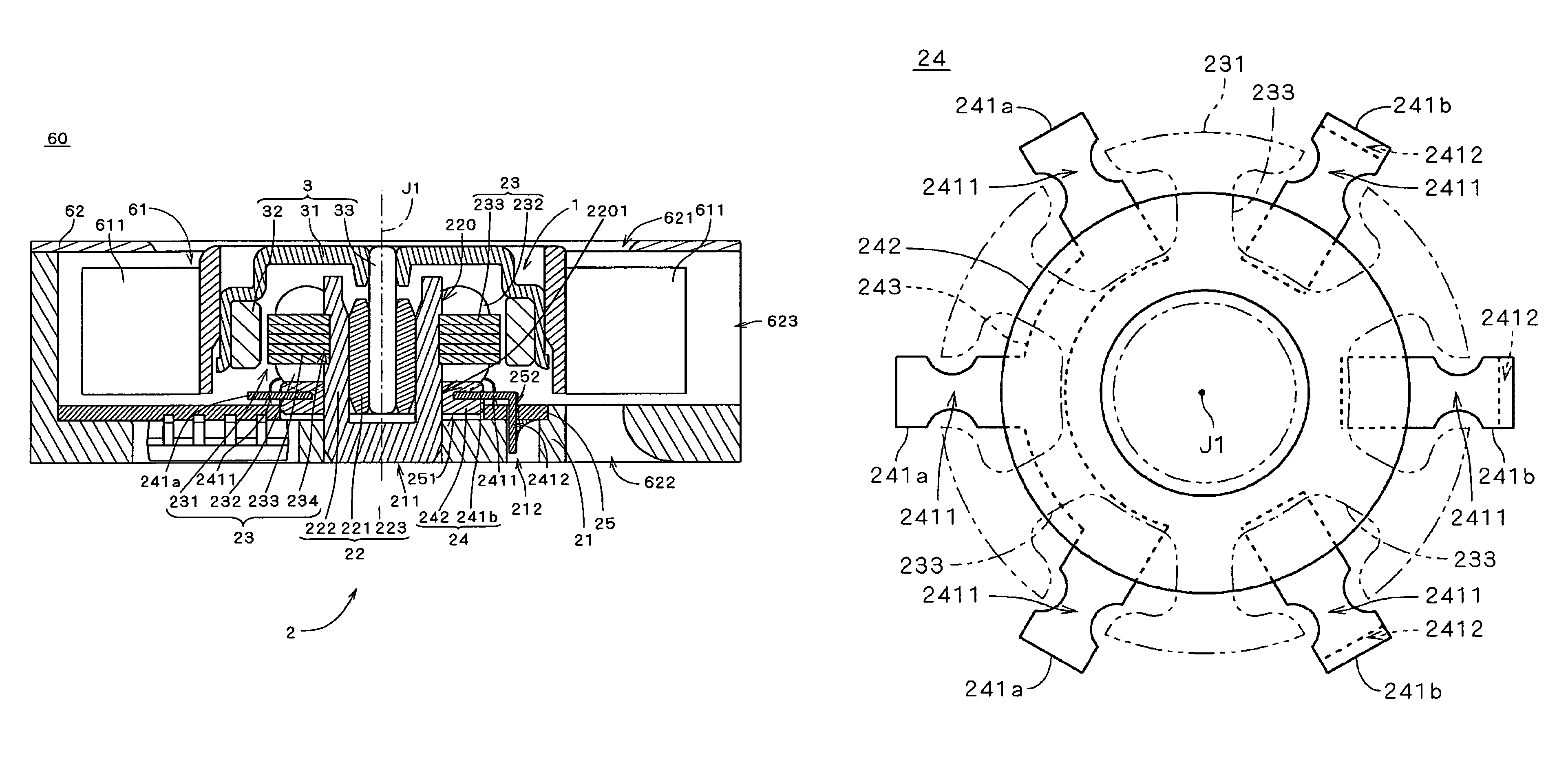
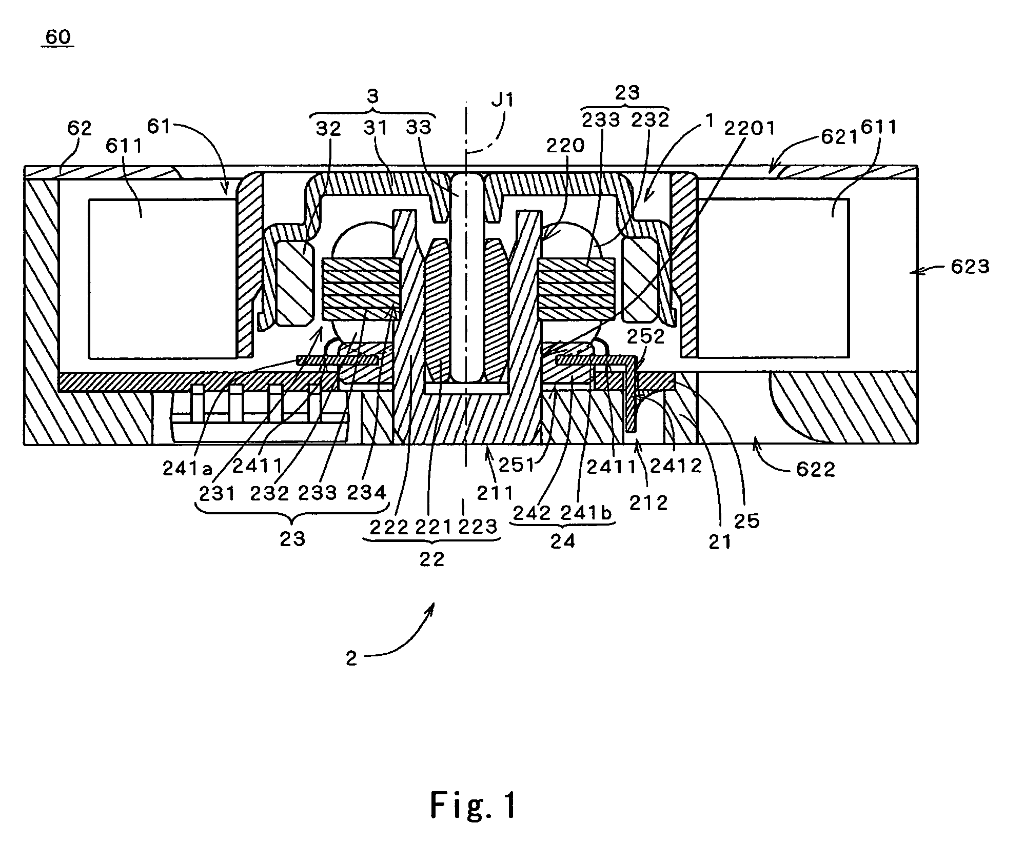
[0024]FIG. 1 is a vertical sectional view of an electrically powered motor 1 along a plane including a center axis J1, illustrating an internal configuration of a centrifugal fan 60 according to a first preferred embodiment of the present invention. The centrifugal fan 60 is, for example, used for an air-cooling fan for an electronic device and includes an impeller portion 61, a small motor 1 and a housing 62.
[0025]The impeller portion 61 rotates and generates air-flow. The impeller portion 61 is attached to the motor 1 and rotated with centering on the center axis J1. The housing 62 surrounds the impeller portion 61 and the motor 1 and defines a passage of the air-flow. Meanwhile, the housing 62 controls the air-flow generated by the rotation of the impeller portion 61 and air is sent forth therethrough.
[0026]As shown in FIG. 1, the motor 1 is an outer rotor motor, and includes a stator unit 2 which is a stationary assembly and a rotor unit 3 which is a rotatable assembly. Via a be...
second embodiment
of the Present Invention
[0080]Next, a micro-motor 1a according to a second preferred embodiment of the present invention will be explained. FIG. 9 is a cross sectional view illustrating the motor 1a. As shown in FIG. 9, the motor 1a includes independent terminal pins 241c which are different in their shape from those illustrated in FIGS. 1 and 3. The rest of the configurations are the same as those illustrated in FIGS. 1 to 3, and are labeled with the same reference marks in the explanation that follows.
[0081]As indicated in FIG. 9, the motor 1a includes the stator unit 2 and the rotor unit 3. The rotor unit 3 is rotatably supported on the stator unit 2, with the center axis J1 as center, via a bearing mechanism employing hydrodynamic pressure by the agency of lubricating oil. The configuration of the bearing mechanism of motor 1a is the same as that described in the first preferred embodiment of the present invention. The rotor unit 3 includes the rotor hub 31 and the shaft 33, and...
third preferred embodiment
[0101]Next, a micro-motor 1b according to a third preferred embodiment of the present invention will be explained. FIG. 10 is a cross sectional view illustrating the motor 1b. As shown in FIG. 10, the motor 1b includes the common terminal pins 241d and independent terminal pins 241e which are different in their shape from those illustrated in FIGS. 1 and 3. The rest of the configurations are the same as those illustrated in FIGS. 1 to 3, and are labeled with the same reference marks in the explanation that follows.
[0102]As shown in FIG. 10, in the terminal 24 of the motor 1b, three terminal pins 241d and three independent terminal pins 241c, which are electrically connected to the coils 232, are provided on the base-side portions of the plurality of the coils 232.
[0103]Each of a plurality of terminal pins 241 (i.e., common terminal pins 241d and independent terminal pins 241e) extends in the radial direction centering on the center axis J1 and includes the wire connecting portion 24...
PUM
| Property | Measurement | Unit |
|---|---|---|
| diameter | aaaaa | aaaaa |
| diameter | aaaaa | aaaaa |
| axial distance | aaaaa | aaaaa |
Abstract
Description
Claims
Application Information
 - R&D
- Intellectual Property
- Life Sciences
- Materials
- Tech Scout
- Unparalleled Data Quality
- Higher Quality Content
- 60% Fewer Hallucinations
Browse by: Latest US Patents, China's latest patents, Technical Efficacy Thesaurus, Application Domain, Technology Topic, Popular Technical Reports.
© 2025 PatSnap. All rights reserved.Legal|Privacy policy|Modern Slavery Act Transparency Statement|Sitemap|About US| Contact US: help@patsnap.com


