Developing roller, process for its production, developing assembly and image forming apparatus

a technology of developing rollers and rollers, which is applied in the direction of shafts, bearings, instruments, etc., can solve problems such as faulty images coming from such adhesion, and achieve the effect of high reliability

Active Publication Date: 2010-06-01
CANON KK
View PDF8 Cites 28 Cited by
  • Summary
  • Abstract
  • Description
  • Claims
  • Application Information

AI Technical Summary

Benefits of technology

[0007]An object of the present invention is to provide a developing roller having a high reliability, a process for its production, and a developing assembly and an image forming apparatus which make use of the developing roller.
[0008]Taking account of the above problem, the present inventors have made many extensive studies in order to obtain a developing roller having a surface to which any components bleeding out of the developer feed roller can not easily adhere. In the course of such studies, the present inventors have considered that the surface free energy of the developing roller is a predominant factor of the disposition of adhesion of such bleeding components. Accordingly, in order to calculate the surface free energy on the basis of the Kitazaki and Hata's theory, the present inventors have measured contact angles to water, diiodomethane and ethylene glycol, of developing rollers having surface layers formed of various polymer materials. Then, they have calculate the surface free energy by using these contact angles, whereas it has been unable to find out any clear relationship between the value of surface free energy and the disposition of adhesion of the bleeding components. More specifically, even in the case of a developing roller having a surface layer with a small surface energy, it has come about in some cases that the bleeding components have adhered to the roller surface to cause faulty images coming from such adhesion. However, in the course of such experiments, the present inventors have discovered that a developing roller having a surface layer which is formed of a urethane resin obtained by allowing the following component (a) to react with the following components (b) to (d) or the following components (b) and (e) and has a surface having a contact angle to ethylene glycol of from 60.0 degrees or more to 90.0 degrees or less and a contact angle to diiodomethane of from 30.0 degrees or more to 38.0 degrees or less cannot necessarily prevent the bleeding components from adhering to the roller surface but can reduce the magnitude of image defects such as banding resulting from the bleeding components having adhered to the roller surface. The present invention has been made on the basis of such a novel finding.

Problems solved by technology

More specifically, even in the case of a developing roller having a surface layer with a small surface energy, it has come about in some cases that the bleeding components have adhered to the roller surface to cause faulty images coming from such adhesion.

Method used


Image

  • Developing roller, process for its production, developing assembly and image forming apparatus
  • Developing roller, process for its production, developing assembly and image forming apparatus
  • Developing roller, process for its production, developing assembly and image forming apparatus

Examples


example 1

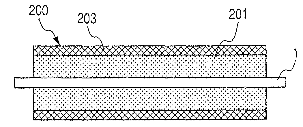
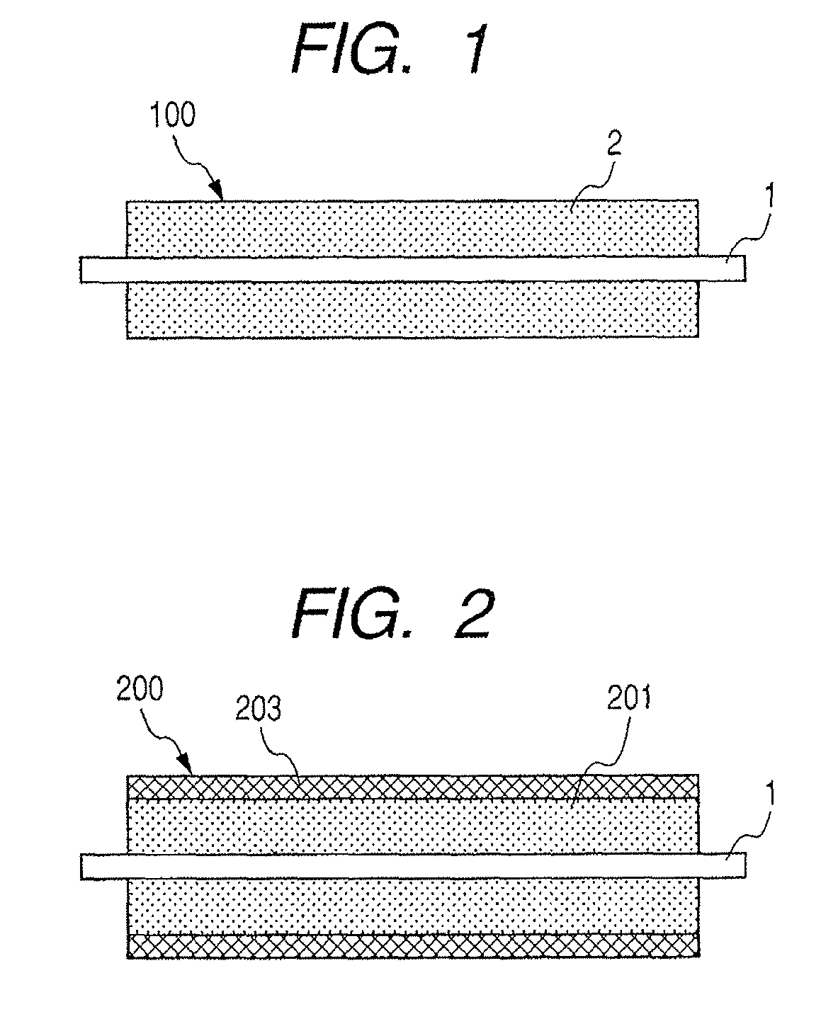
[0108]A mandrel (shaft member) of 8 mm in outer diameter was placed in a cylindrical mold of 16 mm in inner diameter in such a way that they were symmetrical, and a liquid conductive silicone rubber (a product available from Dow Corning Toray Silicone Co., Ltd.; Asker-C hardness: 45 degrees; volume resistivity: 1×10⁷ Ωcm) was casted thereinto as a material for forming an elastic layer. After it was casted thereinto, the mold was put into a 130° C. oven to heat it for 20 minutes. After demolding, the molded product was subjected to secondary vulcanization in a 200° C. oven to form an elastic layer 201 of 4 mm in thickness on the peripheral surface of the mandrel.

[0109]Next, a fluid mixture of the following raw materials was prepared.

[0110]

(by mass)Alcohol (1)100partsAlcohol (3)3.1partsAlcohol (5)2partsIsocyanate C2521 (available from Nippon Polyurethane125partsIndustry Co., Ltd.; solid content: 65%)

[0111]To the fluid raw-material mixture obtained, methyl ethyl ketone (MEK) was added ...


PUM


Abstract

A developing roller having a surface layer which contains a urethane resin composed of a reaction product of an isocyanate with a group of specific alcohols and has a surface having a contact angle to ethylene glycol of from 60.0 degrees or more to 90.0 degrees or less and a contact angle to diiodomethane of from 30.0 degrees or more to 38.0 degrees or less. The developing roller is highly reliable as having controlled banding which is an image difficulty caused at the part of contact between the developing roller and a developer feed roller.

Description

BACKGROUND OF THE INVENTION[0001]1. Field of the Invention[0002]The present invention relates to a developing roller used in, e.g., electrophotographic image forming apparatus such as copying machines and laser beam printers, and also relates to a process for its production, and a developing assembly and an image forming apparatus which make use of the developing roller.[0003]2. Description of the Related Art[0004]Electrophotographic image forming apparatus which employ a pressure development process are known as electrophotographic image forming apparatus such as copying machines, laser beam printers, and receiving sets of facsimile machines. The pressure development process is a development process in which a non-magnetic one-component developer is used as a developer and the developer is made to adhere to an electrostatic latent image held on a photosensitive drum, to render the latent image visible. This process is widely used because it requires no magnetic material, facilitate...

Claims


Application Information

Patent Timeline
Patent Type & Authority Patents(United States)
IPC IPC(8): B05C1/08
CPCG03G15/0818
Inventor NAKAMURA, MINORUWATANABE, MASAHIRONAGAOKA, KAZUAKISATOH, HIDENORI
Owner CANON KK
Why Eureka
Try Eureka