Apparatus and method for heave compensation

a technology of heave compensation and apparatus, which is applied in the direction of floating buildings, underwater structures, artificial islands, etc., can solve the problems of increasing the load, reducing the safety and damage-free manner of the operator, and reducing the tension of the lifting wire. , to achieve the effect of reducing the tension, increasing the tension and reducing the tension

Inactive Publication Date: 2010-06-08
SUBSEA 7 BV
View PDF28 Cites 28 Cited by
  • Summary
  • Abstract
  • Description
  • Claims
  • Application Information

AI Technical Summary

Benefits of technology

[0065]For example, where the output of the lift wire tension measuring device indicates that the tension in the lift wire is increasing, the control device typically pays out wire in order to reduce the tension. Where the output of the lift wire tension measuring device indicates that the tension in the lift wire is decreasing, the control device typically recovers wire in order to increase the tension. The sequence of pay out and recovery operations typically attenuates the tension in the lift wire. Alternatively, or additionally, the sequence of pay out and recovery operations typically attenuates the stretch of the lift wire. This has the advantage that excess energy in the crane or winch system is avoided, which in turn leads to a more stable load.
[0066]For example, where the output of the load motion reference unit indicates that the load is moving so that the tension in the lift wire would increase, the control device typically pays out wire in order to maintain the tension at a level necessary to prevent such load movement. Where the output of the load motion reference uni...

Problems solved by technology

In particular, vertical motion of the top end of the cable or rope translates to an undesirable vertical motion of the suspended load.
Unwanted vertical motion of the suspended load creates two problems in the marine industry.
Firstly, relative motion between the load and the surrounding water introduces additional loads into the system.
Secondly, the uncontrolled vertical motion of the suspended load makes it difficult for an operator to be confident of positioning a load on the seabed, or other landing site, in a safe and damage-free manner.
Thus, the load may be set down too heavily causing damage thereto.
In practice however, it is not generally ...

Method used


Image

  • Apparatus and method for heave compensation
  • Apparatus and method for heave compensation
  • Apparatus and method for heave compensation

Examples


Embodiment Construction

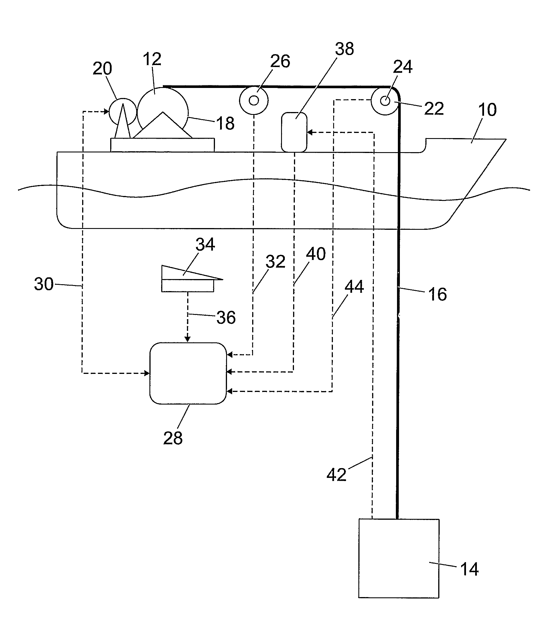
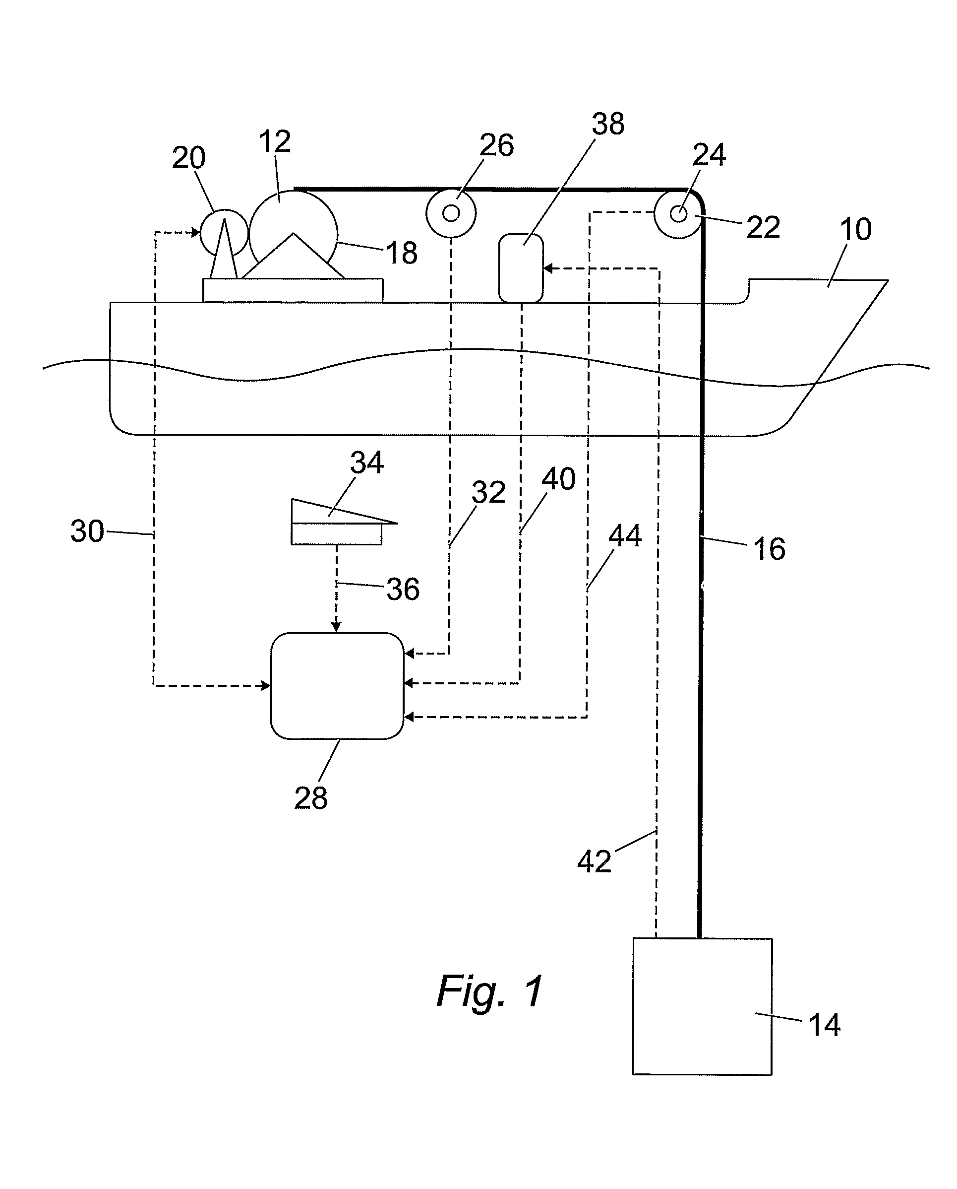
[0082]Referring now to the drawings, FIG. 1 schematically shows an exemplary embodiment of heave compensation apparatus provided on a surface vessel 10. In this embodiment, the vessel 10 is provided with a winch 12 to facilitate lowering a load 14 to a particular depth in the water such as the seabed (not shown) or raising the load 14 therefrom.

[0083]It should be noted that the term “seabed” as used herein will be understood to refer to any underwater bed (e.g. a lake bed, river bed etc.).

[0084]It should also be noted that the load 14 need not be lowered direct to the seabed. In some cases, the load 14 may be lowered onto or raised from other underwater locations, for example apparatus and equipment such as wellheads, manifolds and the like.

[0085]Also, the particular embodiment described herein refers to the use of a winch 12. However, a crane or other lifting apparatus could be provided in place of the winch 12, and embodiments of the present invention can be used with these and ot...


PUM


Abstract

A heave compensation apparatus and method for a winch or crane system, the winch or crane system preferably for a vessel and including a lift wire for attachment to a load. The apparatus includes a vessel motion measurement device which may be in the form of a motion reference unit for measuring the motion of the vessel, and a control device or computer capable of receiving an output from the vessel motion measurement device and controlling the winch or crane system according to the movement of the vessel, so as to stabilise the load. The apparatus may further optionally include one or more of a lift wire tension measuring device for measuring the tension in the lift wire; a lift wire distance measurement device which measures the length of lift wire that has been paid out; and a load motion measurement device for measuring the motion of the load.

Description

FIELD OF THE INVENTION[0001]The present invention relates to apparatus and a method that are particularly, but not exclusively, suited for deep-water heave compensation.DESCRIPTION OF THE RELATED ART[0002]It is common in the marine industry for loads to be lowered from a surface vessel to the seabed. The surface vessel is typically provided with a winch or crane that is capable of lowering a load to the seabed, or raising a load therefrom. As the vessel floats on the sea, the wave action of the sea causes vessel motions, which in turn cause motion of the top end of the lowering cable or rope. In particular, vertical motion of the top end of the cable or rope translates to an undesirable vertical motion of the suspended load.[0003]Unwanted vertical motion of the suspended load creates two problems in the marine industry. Firstly, relative motion between the load and the surrounding water introduces additional loads into the system. Secondly, the uncontrolled vertical motion of the su...

Claims


Application Information

Patent Timeline
IPC IPC(8): B66D1/00B66D1/52
CPCB66D1/525B66D1/485B66D1/48B66D1/52
Inventor DAVIDSON, DANIEL
Owner SUBSEA 7 BV
Why Eureka
Try Eureka