Check patentability & draft patents in minutes with Patsnap Eureka AI!

Temperature independent delay circuits

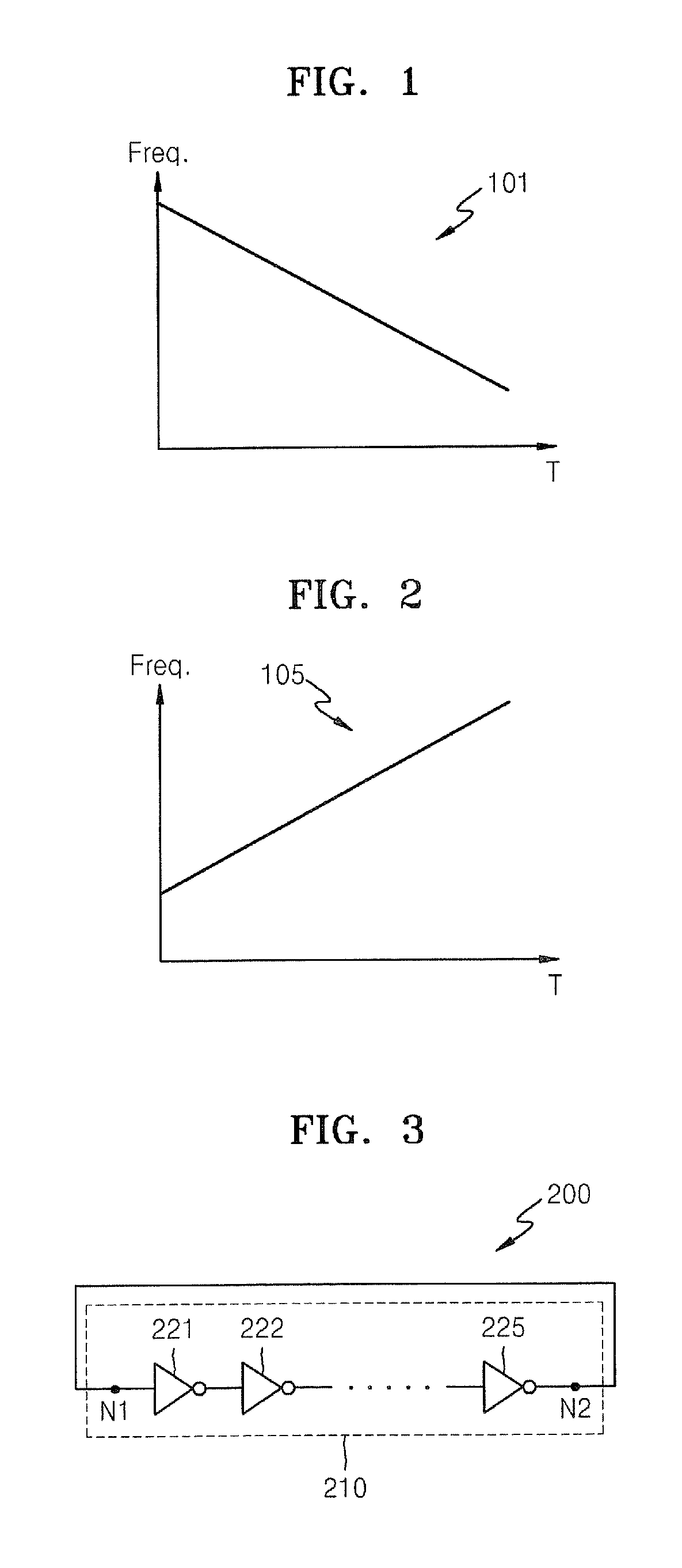
a delay circuit and temperature-dependent technology, applied in the field of electric circuits, can solve the problems of disadvantageous lowering of the operating frequency of the ring oscillator, increase in the clock signal generating period t, and disadvantageous generating of the general ring oscillator b>200/b>

Active Publication Date: 2010-06-08
SAMSUNG ELECTRONICS CO LTD
View PDF8 Cites 3 Cited by
  • Summary
  • Abstract
  • Description
  • Claims
  • Application Information

AI Technical Summary

Benefits of technology

The solution effectively stabilizes the delay time across temperature variations, enabling high-speed operation and maintaining frequency stability without being limited by voltage ranges, thus improving the performance of integrated circuits.

Problems solved by technology

A general ring oscillator 200 may have a disadvantage in terms of generating a clock signal.
The increase in delay time may lead to an increase in clock signal generating period T. Therefore, as the delay time is increased, the operating frequency of the ring oscillator may be disadvantageously lowered.
Therefore, if the increase in delayed amount is not compensated according to an increase in temperature, the ring oscillator may not be normally operated.
However, the method of increasing bias voltages may include limitations corresponding to low voltage operation and / or a high-speed operation.
In this regard, a high speed operation may not be obtained.

Method used


Image

  • Temperature independent delay circuits
  • Temperature independent delay circuits
  • Temperature independent delay circuits

Examples


Embodiment Construction

[0028]The present invention now will be described more fully hereinafter with reference to the accompanying drawings, in which embodiments of the invention are shown. However, this invention should not be construed as limited to the embodiments set forth herein. Rather, these embodiments are provided so that this disclosure will be thorough and complete, and will fully convey the scope of the invention to those skilled in the art.

[0029]It will be understood that, although the terms first, second, etc. may be used herein to describe various elements, these elements should not be limited by these terms. These terms are only used to distinguish one element from another element. Thus, a first element discussed below could be termed a second element without departing from the scope of the present invention. In addition, as used herein, the singular forms “a”, “an” and “the” are intended to include the plural forms as well, unless the context clearly indicates otherwise. It also will be u...


PUM


Abstract

Delay circuits are provided. Some embodiments of delay circuits herein include a delay line including multiple delay cells connected in series and a variable voltage supplier operative to output a voltage value proportional and / or inversely proportional to a temperature. Delay circuits may include at least one loading capacitor that includes a first end that is connected to an output port of the delay cell and a second end that is connected to an output port of the variable voltage supplier, the at least one loading capacitor including a capacitance that is decreased corresponding to an increase in temperature when a positive voltage is applied across the first end and the second end of the at least one loading capacitor.

Description

CROSS-REFERENCE TO RELATED PATENT APPLICATION[0001]This application claims the priority of Korean Patent Application No. 10-2007-0106209, filed on Oct. 22, 2007, in the Korean Intellectual Property Office, the disclosure of which is incorporated herein in its entirety by reference.BACKGROUND OF THE INVENTION[0002]The present invention relates to electrical circuits, and more particularly, to a integrated electrical circuits.[0003]In some integrated circuits (ICs), complicated circuit components operating with various signals and information may be integrated. An IC may use one or more clock signals to control complicated operations of the circuit components and adjust operating timings thereof. In applications of communication, signal processing, and the like, the IC may use signal sources and signal source generators as well as the clock signals. Circuit designers may benefit from a clock generation circuit and a signal source circuit that can be adapted to various circuits, proces...

Claims


Application Information

Patent Timeline
Patent Type & Authority Patents(United States)
IPC IPC(8): H03H11/26
CPCH03K3/0315H03K5/133H03K2005/00143G11C11/407G11C11/406
Inventor KIM, HYUNG-SEUK
Owner SAMSUNG ELECTRONICS CO LTD
Features
  • R&D
  • Intellectual Property
  • Life Sciences
  • Materials
  • Tech Scout
  • Unparalleled Data Quality
  • Higher Quality Content
  • 60% Fewer Hallucinations
Learn More