
Microclimate regulating garment and composite structure

a technology of microclimate and garment, applied in the field of active protective apparel, can solve the problems of garments being more rigid than others, limited breathability of such foam, and limited design utility as a field item, and achieve the effects of preventing the trapping of moisture in the garment, reducing wear cycle time, and high moisture vapor transpor

Inactive Publication Date: 2010-06-15
CLEMSON UNIV RES FOUND
View PDF15 Cites 18 Cited by
  • Summary
  • Abstract
  • Description
  • Claims
  • Application Information

AI Technical Summary

Benefits of technology

[0006]The present invention provides a breathable insulative garment containing zones of high moisture vapor transport, which prevents trapping moisture in the garment that lessens wear-cycle time due to saturation and limits promotion of microbial growth. The present invention allows long-term use in the field due to the design and properties of the garment. In particular, the present invention also provides passageways within a garment through which a fluid, liquid or gas can flow, even in the event of a compression of the passageway. Additional advantages of the invention will be set forth in part in the following description, may be obvious from the description, or may be learned through practice of the invention.
[0008]The passageway contains within its walls a filler material which allows a convoluted flow of fluid through the passageway. The filler material is a textile material, preferably fibers, yarn, a web, a batting or a fabric such as a knit, woven or nonwoven structure that adds stability to the passageway walls. Further, porosity of the filler material, as a grouping of parts within the passageway walls or individually, permits the fluid to flow through the filler material as it flows through the passageway. The filler material slows the flow of the fluid while not substantially impeding the flow therethrough. The outer cover material which forms the passageway forms a pattern over the surface area of the first substrate layer in such a manner that the composite structure can be used to control the microclimate surrounding the structure.
[0010]The method of manufacturing a garment for providing microclimate control to the wearer includes providing a first substrate layer panel. An outer cover material is secured to the first substrate layer panel in a manner that the outer cover material forms at least one passageway over a surface area of the first substrate layer panel so that the garment can effectively regulate the microclimate surrounding portions of the wearer's body covered by the garment. A filler material having a porosity to allow a fluid to flow therethrough is placed under the outer cover material, between two pieces of the outer cover material before the passageway is formed, or may be placed in the passageway after the passageway is formed. The garment is formed by attaching the first substrate layer panels together as needed to create the garment. The first substrate layer panels may be attached together to form the basic shape of the garment before the outer cover material is secured to the substrate layer panels which forms the passageways containing the filler material. Further, the garment may be made of one substrate layer panel.
[0012]One method that may be used to make a composite structure for providing microclimate control to the wearer includes providing a non-thermoplastic first substrate layer having a front side and a back side. A thermoplastic filler material is laid over the front side of the first substrate layer. A thermoplastic outer cover material is placed over the filler material, so that the filler material is between the first substrate and the outer cover material. The outer cover material and the filler material are then cut with a thermal device in a manner that an enclosed passageway is formed with the outer cover material containing the filler material within the passageway walls. The thermal device melts the edges of outer cover material thereby causing the melted edges to interlock with the non-thermoplastic first substrate layer forming a composite fabric with passageways containing the filler material. Appropriate first substrate layers can then be sewn together to form a desired garment. Also as above, the garment may be made from a single first substrate layer by cutting the pattern of the garment out of a single composite fabric structure and properly sewing or attaching the appropriate ends of the cut composite fabric structure forming the garment.

Problems solved by technology

The breathability of such foam is limited.
Obviously, this design has limited utility as a field item and would be for short-term, acute use only.
A pressure required to pump the fluid through such a system can cause problems.
The pressure causes the garment to be more rigid than is desirable and puts a large stress in the channel walls.
This part of the fluid flow does not aid in the transfer of heat in relation to the wearer's body.
By fulfilling the purpose of maintaining the desired shape of the channels, the closed cell foam ribbon can actually isolate that part of the fluid flow, rendering it useless.

Method used


Image

  • Microclimate regulating garment and composite structure
  • Microclimate regulating garment and composite structure
  • Microclimate regulating garment and composite structure

Examples


Embodiment Construction

[0023]Reference will now be made in detail to the presently preferred embodiments of the invention, one or more examples of which are shown in the figures. Each example is provided to explain the invention and not as a limitation of the invention. In fact, features illustrated or described as part of one embodiment can be used with another embodiment to yield still a further embodiment. It is intended that the present invention cover such modifications and variations.

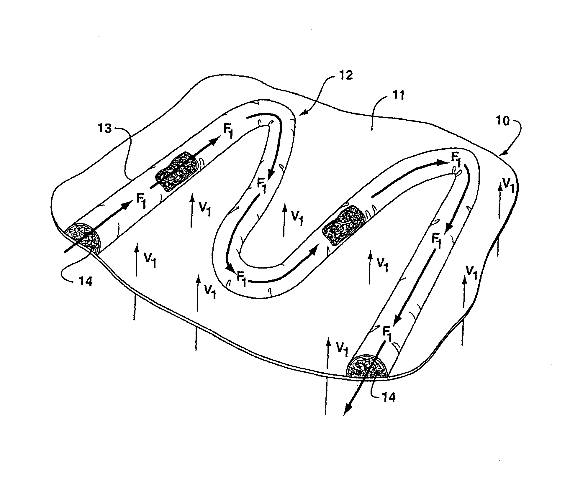
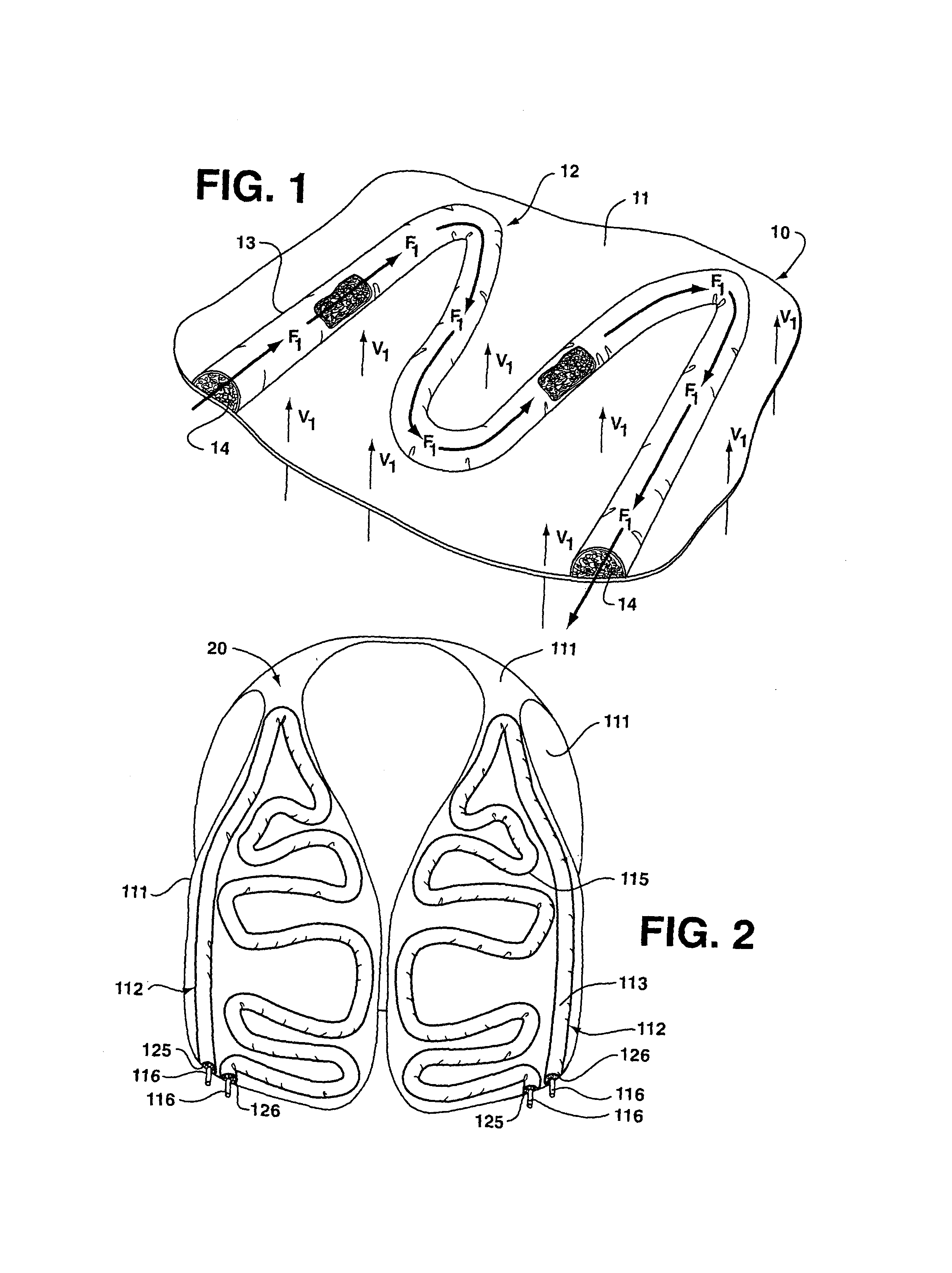
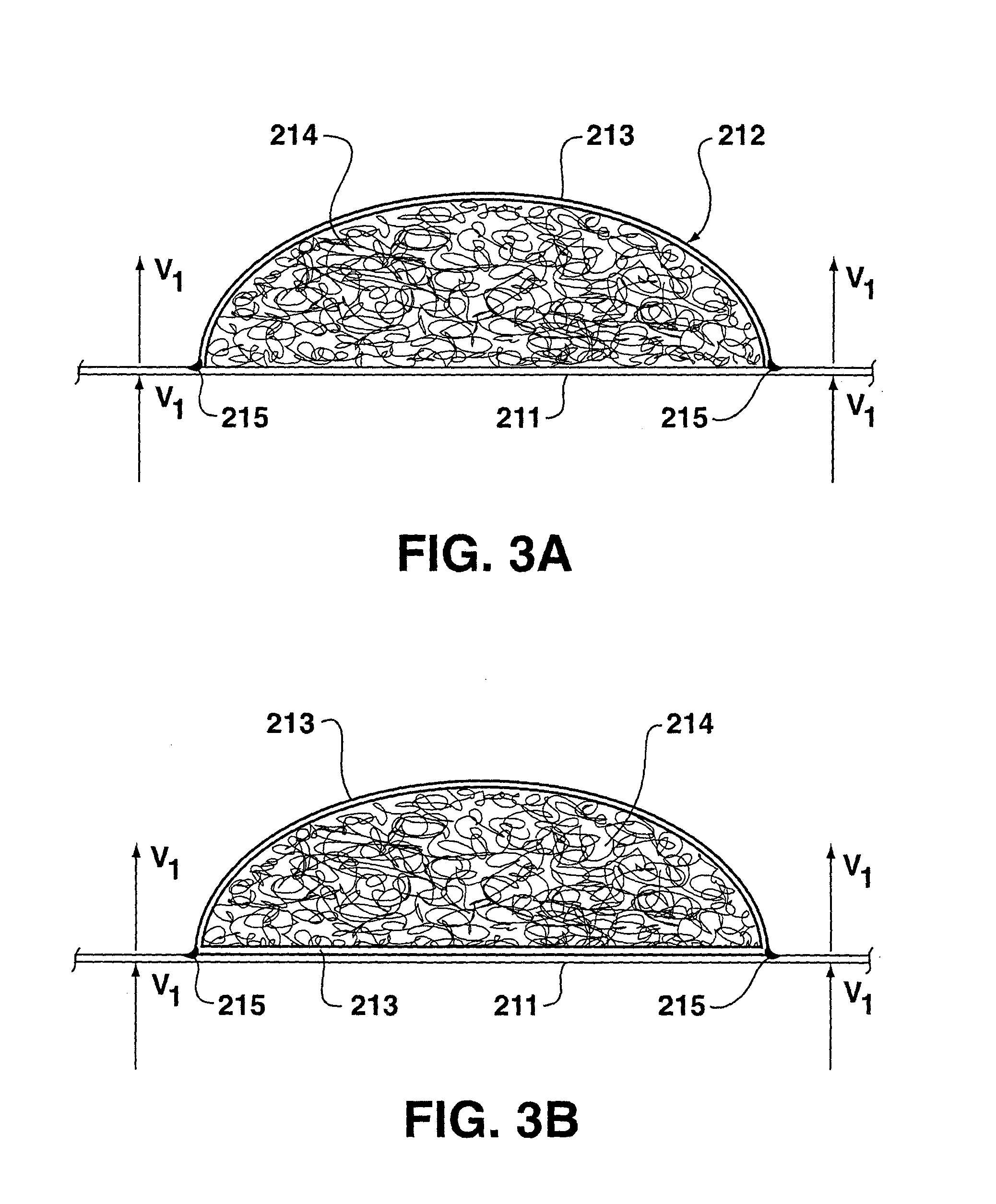
[0024]FIG. 1 illustrates a composite structure 10 representing an embodiment of the present invention. Preferably, the composite structure 10 is a composite fabric. Composite structure 10 has a first substrate layer 11. At least one enclosed passageway 12 is formed by attaching an outer cover material 13 to first substrate layer 11 in a pattern over first substrate layer 11. The outer cover material 13 creates at least part of the walls of the passageways. The walls of passageway 12 contain a filler material 14 within t...


PUM

PropertyMeasurementUnit
Acoustic impedanceaaaaaaaaaa
Flow rateaaaaaaaaaa
Structureaaaaaaaaaa

Abstract

This invention is for a composite structure and a garment constructed from the composite structure which can be worn next to the skin or as outerwear as well as a process for making the composite structure and garment. The garment provides microclimate control for the wearer by means of at least one three-dimensional passageway formed by an outer cover material which is secured to a first substrate layer. The passageway contains a filler material which adds support to the walls of the passageways and allows a fluid to flow through the filler material. The passageway provides a thermal insulation by its bulk or by allowing a fluid to be pumped through it. The first substrate layer is breathable to increase the comfort level of the wearer.

Description

FEDERALLY SPONSORED RESEARCH OR DEVELOPMENT[0001]Research through which this invention was developed was sponsored by a grant from the National Institute of Justice under grant no. MIPT 106-113-2000-21.BACKGROUND OF THE INVENTION[0002]In the area of active protective apparel, a need exists for improved, lightweight, multifunctional garments and equipment which can be worn in changing environments for extended periods of time. A single unit or garment is desirable that is adaptable to a variety of challenges, reducing the necessity of carrying additional specialized units and meeting the requirements of low bulk and weight. Such a garment would be useful for emergency responders and military personnel, as well as for persons involved in other outdoor activities.[0003]The provision of a microclimatizing garment capable of insulating against temperature extremes, while also maintaining comfort and health by promoting normal moisture evaporation from the skin, represents an advancement ...

Claims


Application Information

Patent Timeline
IPC IPC(8): A41D13/00A41D13/002A41D13/005A41D27/28A41D31/00A41D31/02A47G9/02A62B17/00B32B3/08B32B5/26D06M17/00
CPCA41D13/0025A41D31/0038B32B5/26A62B17/005B32B3/08A47G9/0215A41D31/065Y10T442/60B32B5/022B32B5/026B32B2307/7265B32B2571/00
Inventor JARVIS, CHRISTINE W.
Owner CLEMSON UNIV RES FOUND
Learn More