Engine cooling system with overload handling capability

a technology of engine cooling system and overload handling, which is applied in the direction of machines/engines, indirect heat exchangers, light and heating apparatus, etc., to achieve the effect of facilitating the downsizing of automotive engines without restricting peak performance, simple, compact and lightweigh

Inactive Publication Date: 2010-06-15
AGWEST
View PDF14 Cites 47 Cited by
  • Summary
  • Abstract
  • Description
  • Claims
  • Application Information

AI Technical Summary

Benefits of technology

[0012]The heat accumulator in accordance with the subject invention contains PCM in thermal contact with the coolant. The PCM has a solid-to-liquid transition (melting) temperature Tmelt which is higher than the normal operating temperature T0 of the liquid coolant but lower than the temperature Trelief at which a coolant pressure relief valve in the system opens. Because the heat accumulator averages out certain peak heat loads to the cooling system, the system's requirement to transfer heat to ambient air may be reduced so as to handle only an average rather than a peak heat load. As a result, the size and weight of engine cooling system may be substantially reduced. This is particularly important for improving fuel economy and reduction of emission in automotive vehicles. See, for example, “Innovative Engine Cooling Systems Comparison,” by N. S. Ap and M. Tarquis, a Technical Paper No. 2005-01-1378 presented at the SAE World Congress in Detroit, Mich., Apr. 11-14, 2005, available from SAE International, Warrendale, Pa. In addition, the invention enables reducing the coolant inventory in the system thereby allowing for faster ICE warm-up and reduced emissions of harmful pollutants during a cold engine start.
[0020]It is still another object of the present invention to provide an engine cooling system that has a low coolant inventory and thus allows quick warm-up during cold engine start.

Problems solved by technology

In automotive vehicles, the heat accumulator may store excess ICE heat generated during vehicle acceleration or hill climbing, and it may dissipate stored heat during reduced heat load conditions such as vehicle cruise, deceleration, or idle.

Method used


Image

  • Engine cooling system with overload handling capability
  • Engine cooling system with overload handling capability
  • Engine cooling system with overload handling capability

Examples


Embodiment Construction

[0029]Selected embodiments of the present invention will now be explained with reference to drawings. It will be apparent to those skilled in the art from this disclosure that the following descriptions of the embodiments of the present invention are merely exemplary in nature and are in no way intended to limit the invention, its application, or uses.

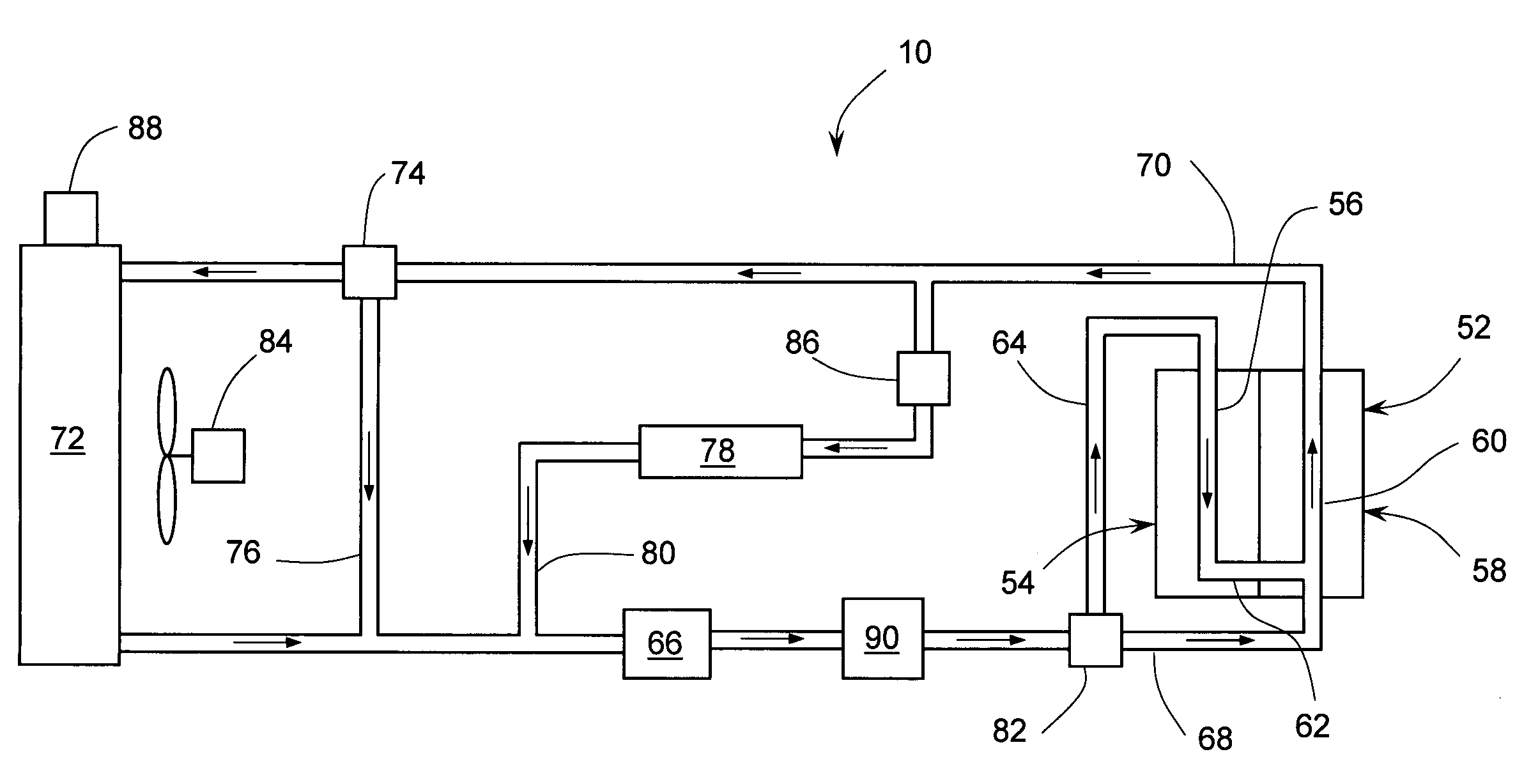
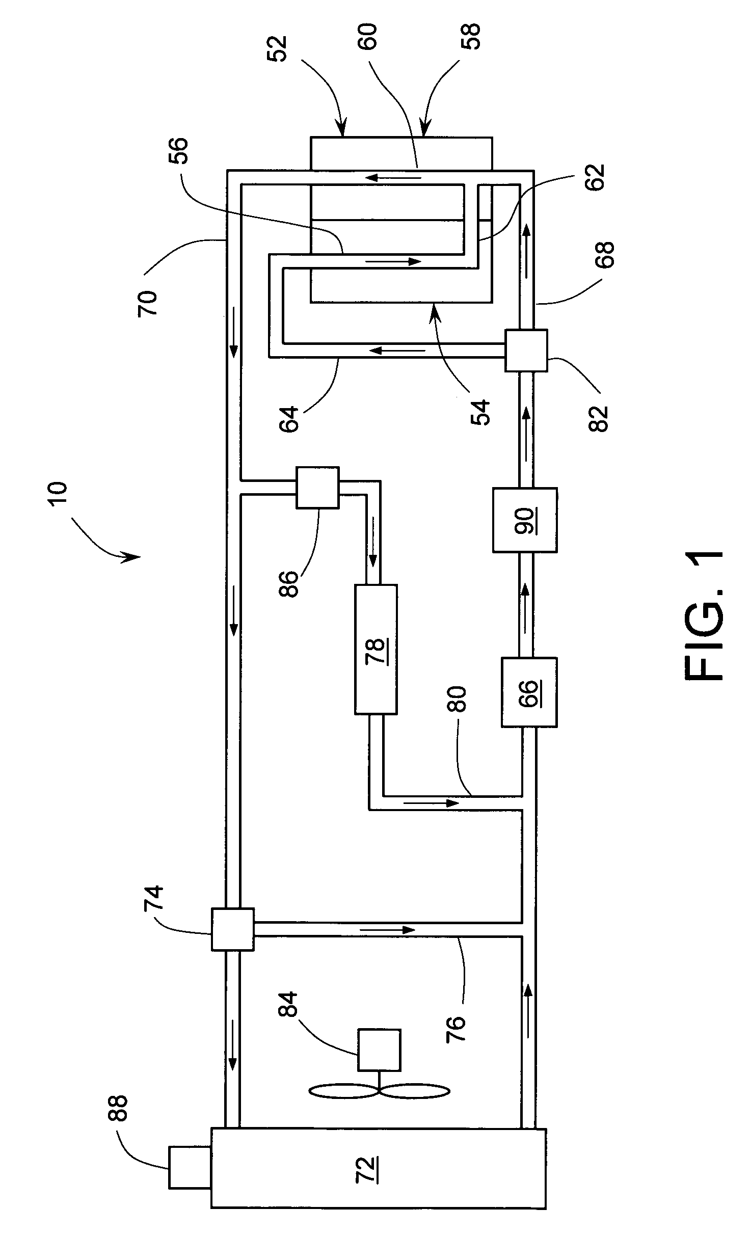
[0030]Referring to FIG. 1 of the drawings in detail, numeral 10 generally indicates a cooling system for an internal combustion engine (ICE). The cooling system 10 generally comprises an engine 52, radiator 72, water pump 66, heat accumulator 90 and interconnecting lines. Components of the cooling system 10 are fluidly connected so that the water pump 66 may circulate liquid coolant between the engine 52 and the radiator 72. Direction of coolant flow is indicated by arrows. The engine 52 may further comprise a cylinder block 54 and a cylinder head 58 mounted on the cylinder block. The cylinder block 54 has a cooling jacket 56 and the c...


PUM


Abstract

A cooling system for an internal combustion engine incorporating a heat accumulator to temporarily store heat during peak heat loads. In automotive vehicles, the heat accumulator may store excess heat generated during vehicle acceleration or hill climbing and it may dissipate stored heat during vehicle cruise, deceleration, or engine idle. The heat accumulator contains phase change material with a solid-to-liquid transition temperature higher than the normal operating temperature of the cooling system. The invention enables reducing the size and weight of engine cooling system without compromising its performance. This is particularly important for improving fuel economy and reduction of emission in automotive vehicles. In addition, the invention enables reducing the coolant inventory in the system thereby allowing for faster engine warm-up and reduced emissions of harmful pollutants during a cold engine start. The invention may be also used for thermal management of engine oil, transmission fluid, or hydraulic fluid.

Description

FIELD OF THE INVENTION[0001]The present invention generally relates to thermal management of fluid systems for internal combustion engines and more particularly to providing engine fluid systems with capability to handle thermal overloads.BACKGROUND OF THE INVENTION[0002]An internal combustion engine (ICE) commonly employs a pressurized cooling system with a circulating liquid coolant for cooling the engine. Waste heat is transferred from the ICE to the coolant in a cooling jacket(s) surrounding combustion heated parts of the engine. The heat absorbed by the circulated coolant is generally dissipated by a heat exchanger into the air. This heat exchanger, also known as a “radiator”, may also operate with a cooling fan which blows air into the heat exchanger thereby promoting heat transfer from liquid coolant to air.[0003]Scaling Considerations for Engine Cooling Systems: The design capacity of ICE cooling system is traditionally determined according to the cooling capacity needed for...

Claims


Application Information

Patent Timeline
Patent Type & Authority Patents(United States)
IPC IPC(8): F01P11/02
CPCF01P11/20F28D20/021F28F1/40F01P2003/027F01P2003/028F01P2011/205F28F2225/04Y02E60/145F01P2060/08Y02E60/14
Inventor VETROVEC, JAN
Owner AGWEST
Why Eureka
Try Eureka