Eureka AIR delivers breakthrough ideas for toughest innovation challenges, trusted by R&D personnel around the world.

High-pressure fuel supply apparatus and control apparatus for internal combustion engine

a fuel supply apparatus and high-pressure technology, applied in the direction of electric control, muscle operated starters, instruments, etc., can solve the problems of increasing the weight of the pressure control valve, the inability to mount the pressure control valve on the automobile, and the large amount of direct injection of the internal combustion engine, so as to prevent the enlargement of the high-pressure fuel supply apparatus, improve the emission gas performance, and reduce the effect of enlargemen

Inactive Publication Date: 2010-06-15
HITACHI LTD
View PDF17 Cites 8 Cited by
  • Summary
  • Abstract
  • Description
  • Claims
  • Application Information

AI Technical Summary

Benefits of technology

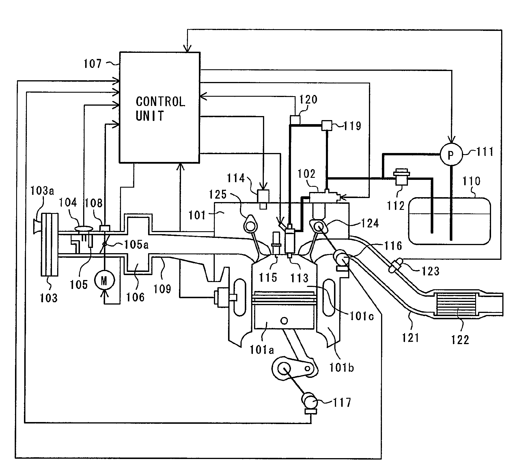
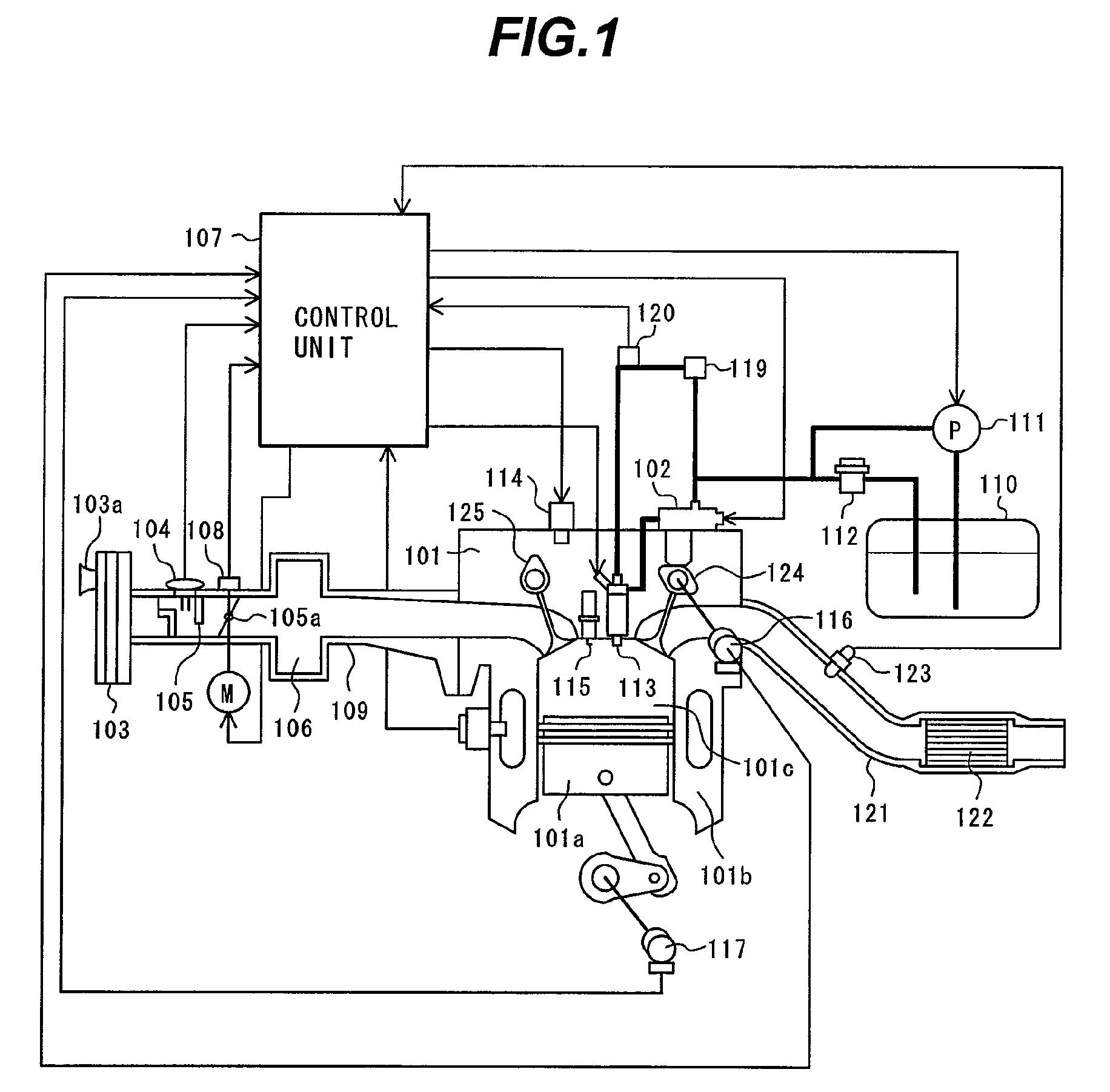
[0012]Japanese Patent No. 3972823 assumes a zone equal to or lower than the pressure control valve opening-pressure. Japanese Patent No. 3972823 gives no particular consideration to the maximum fuel pressure point of the high-pressure fuel apparatus device but aims to provide means for avoiding the abnormal high-pressure state.
[0013]The present inventor considers the following. An apparatus prevents a pressure control valve from increasing in size and is such that the maximum fuel pressure point of an common rail exceeds the limit pressure of an injector when a high-pressure fuel apparatus device causes malfunction. In this apparatus, the maximum fuel pressure point encountered when malfunction occurs should not be determined from reliability degradation pressure of a apparatus-constituent part. In contrast, the maximum fuel pressure point should be set from pressure that does not affect a flow characteristic (energization time—injection quantity characteristic) and a spray characteristic (spray shape and a spray angle) when malfunction of the injector is corrected after the experience of an abnormal pressure rising.
[0028]The high-pressure fuel supply apparatus and the control apparatus for an internal combustion engine configured as described above according to the present invention do not change the flow characteristic and spray characteristic of the injector even after recovery from the malfunction of the apparatus while preventing enlargement of the high-pressure fuel supply apparatus. This contributes to stable combustion and to an improvement in emission gas performance.
[0029]According to the present invention, the high-pressure fuel supply apparatus and the control apparatus for an internal combustion engine do not change the flow characteristic and spray characteristic of the injector even after causing malfunction to increase the pressure and then recovering from the malfunction of the high-pressure fuel supply apparatus or the control apparatus thereof while preventing the high-pressure fuel supply apparatus from being excessively increased in size. Such a apparatus or device is provided which maintains the flow characteristic and spray characteristic of the injector significantly affecting the combustion of the direct injection internal combustion engine. This contributes to stable combustion and to an improvement in emission gas performance.

Problems solved by technology

However, today's direct-injection internal combustion engines need a large amount of discharge and high fuel pressure.
This may poses a problem in that the pressure control valve cannot be mounted on an automobile or is increased in weight.

Method used


Image

  • High-pressure fuel supply apparatus and control apparatus for internal combustion engine
  • High-pressure fuel supply apparatus and control apparatus for internal combustion engine
  • High-pressure fuel supply apparatus and control apparatus for internal combustion engine

Examples


first embodiment

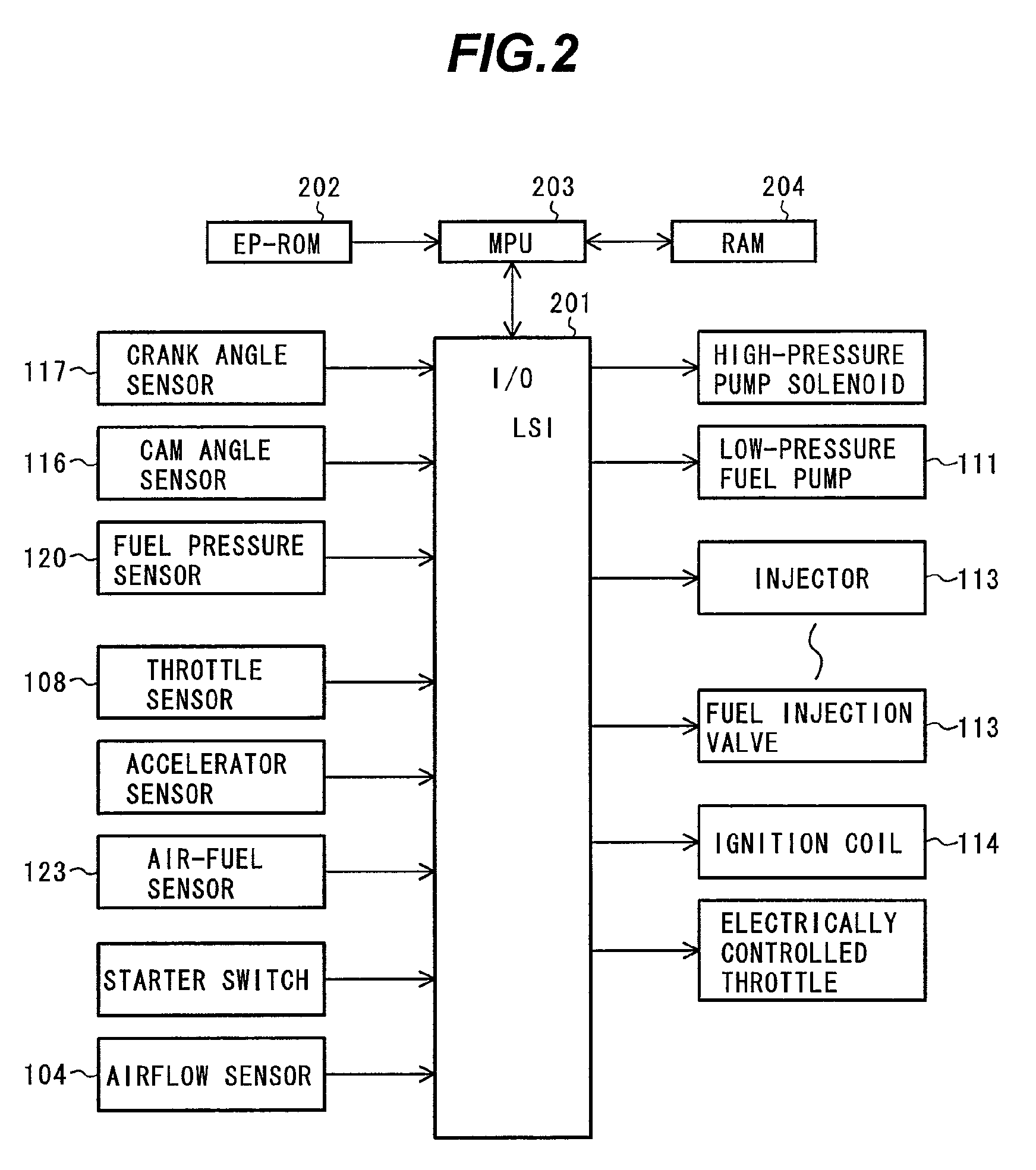
[0069]FIG. 9 illustrates a control flowchart of the control apparatus for the internal combustion engine according to the present invention. Interrupt processing is started at block 901. The interrupt processing may be done based on temporal synchronization such as, e.g., every 10 ms or on a rotational period such as, e.g., every 180 degrees of crank angle.

[0070]At block 902, malfunction of a fuel pressure sensor provided in the common rail is detected. The malfunction detected at block 902 is such that the voltage of the fuel pressure sensor keeps an upper limit (fuel pressure higher than the actual fuel pressure is recognized). The malfunction is detected, for example, based on whether an input value of the fuel pressure sensor remains unchanged for a certain period of time. Block 902 aims to prevent engine stall caused by the fact that fuel pressure is erroneously recognized due to the malfunction of the fuel pressure sensor so that fuel cut relating to the present invention desc...

second embodiment

[0076]FIG. 11 illustrates a control flowchart of the prescribed value calculation means 910 according to a Interrupt processing is started at block 1101 and the required injection quantity (INJR) of the internal combustion engine is read at block 1102.

[0077]Prescribed values (PDIFF) are calculated at block 1103. The prescribed values (PDIFF) are subjected to table retrieval for example. Injector required energization time can be calculated by reading the required injection quantity. The prescribed values (PDIFF) are set so that short energization time may not make the injection quantity unstable. The energization time is more liable to be short as the required injection quantity is smaller. Thus, the injection quantity unstable region is avoided by setting the prescribed values (PDIFF) at larger values with the less required injection quantity.

[0078]A combination of the embodiment shown in FIG. 10 with the embodiment shown in FIG. 11 can calculate prescribed values (PDIFF) used to ...


PUM


Abstract

In an internal combustion engine provided with a high-pressure fuel pump, if the discharging rate of the high-pressure fuel pump is greater than the injection quantity of fuel injected from a injector with the high-pressure fuel pump remaining uncontrollable due to failure or the like, it is probable that the fuel pressure in a common rail unintentionally rises to affect the injector. A high-pressure fuel supply apparatus is provided to solve such a problem.A high-pressure fuel supply apparatus according to the present invention is configured such that if the high-pressure fuel supply apparatus or a control apparatus thereof causes malfunction to increase the pressure in the common rail, the pressure in the common rail does not exceed pressure affecting the flow characteristic and spray characteristic of the injector after recovery from the malfunctioning state.

Description

BACKGROUND OF THE INVENTION[0001]1. Field of the Invention[0002]The present invention relates generally to apparatuses for an internal combustion engine and particularly to a high-pressure fuel supply apparatus.[0003]2. Description of the Related Art[0004]Recently, in spark-ignition engines such as gasoline engines, the technologies of direct injection internal combustion engines have been developed to improve fuel consumption and emission gas performance thereof by supplying fuel under pressure by a high-pressure pump and directly injecting the pressurized fuel into a combustion chamber.[0005]To directly injecting fuel into the combustion chamber as mentioned above, the high-pressurized fuel is handled. This needs a high-pressure fuel supply apparatus. Proposals are made for such technologies.[0006]Japanese Patent No. 3836399 intends to provide a fuel apparatus, for an internal combustion engine, of a type including a fuel container; a fuel pump; a fuel collecting passage adapted t...

Claims


Application Information

Patent Timeline
Patent Type & Authority Patents(United States)
IPC IPC(8): F02M1/00F02N1/00
CPCF02D41/22F02D41/3836F02M2200/18F02D2041/224
Inventor OKAMOTO, TAKASHITSUKADA, SHINSAKUEHARA, HIDEHARUTOYOHARA, MASAHIRO
Owner HITACHI LTD
Why Eureka
Eureka Blog
Learn More