Virtual power rail modulation within an integrated circuit

a virtual power rail and integrated circuit technology, applied in logic circuits, ac network voltage adjustment, electric variable regulation, etc., can solve the problems of circuit area overhead, loss of logic state, and long time to restore this state, so as to reduce power consumption and reduce power consumption. the effect of the integrated circuit and the effect of good

Inactive Publication Date: 2010-06-15
ARM LTD
View PDF13 Cites 49 Cited by
  • Summary
  • Abstract
  • Description
  • Claims
  • Application Information

AI Technical Summary

Benefits of technology

[0011]The present technique recognizes that it is possible to use the virtual power rail architecture within integrated circuits in a more sophisticated way than simply connecting the virtual power rail to the power supply (e.g. via a power rail or a ground rail) during normal operation and isolating the virtual power rail from the power supply during low power operation. More particularly, the present technique recognizes that by modulating (switching on and off repeatedly) the connection between the power supply, and the virtual power rail the virtual power rail can be controlled to adopt voltage levels that can be used to reduce power consumption within the integrated circuit.
[0028]Viewed from a further aspect the present invention provides a method of reducing power consumption of an integrated circuit having a power supply switchably connected to a virtual power rail and with a logic block drawing power from said virtual power rail, said method comprising:

Problems solved by technology

While the above approach is successful, it suffers from the problem that state (e.g. data values, instruction values, configuration etc) within the logic blocks is lost when they are isolated from the power supply.
Furthermore, it can take a disadvantageously long period of time to restore this state and recommence processing using the logic blocks when it is desired to switch out of the low power mode.
A problem with this approach is the overhead associated with the circuit area of the balloon latches, the control thereof and the time taken to restore the signal values from the balloon latches into the logic blocks.

Method used


Image

  • Virtual power rail modulation within an integrated circuit
  • Virtual power rail modulation within an integrated circuit
  • Virtual power rail modulation within an integrated circuit

Examples


Embodiment Construction

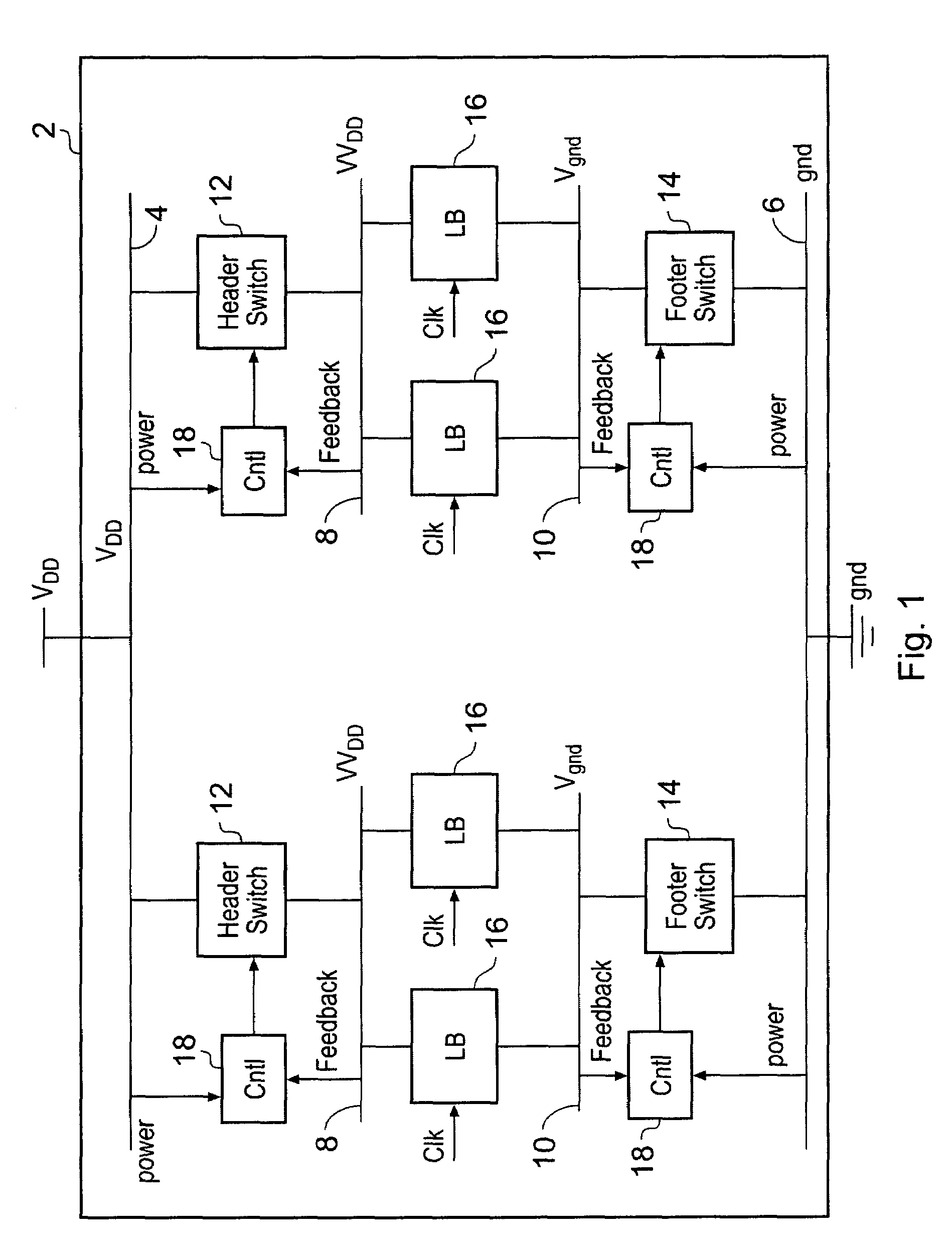
[0036]FIG. 1 illustrates an integrated circuit 2 including a main supply rail 4, a main ground rail 6, a virtual supply rail 8 and a virtual ground rail 10. Header switches 12 selectively connect the main supply rail 4 to the virtual supply rail 8. Similarly, footer switches 14 selectively connect the main ground rail 6 to the virtual ground rail 10. Logic blocks 16 draw their power supply from the virtual supply rail 8 and the virtual ground rail 10. The logic blocks 16 are clocked with a clock signal clk to perform data processing operations.

[0037]The integrated circuit 2 can be formed using different fabrication technologies but the present technique is well suited to systems in which the integrated circuit is formed of CMOS transistors, and more particular MTCMOS transistors. It will be appreciated that the integrated circuit 2 will typically be formed of a large number of functional elements and can take a variety of different forms, such as a microprocessor, a SoC, a memory or...


PUM


Abstract

An integrated circuit is provided with logic blocks which draw their power from virtual supply rails. These virtual supply rails are connected by switch blocks to main supply rails. The switch blocks are subject to modulation to maintain the virtual supply rails at an intermediate voltage level such that a reduced voltage difference is applied across the logic block. This intermediate voltage level is used in a state retention mode in which the clock signal clk to the logic block is stopped and state signal values are maintained therein using this reduced virtual power rail derived voltage difference. When it is desired to resume processing then the full virtual rail voltages are restored by rendering the switch blocks fully conductive and then the clock is restarted. The switch blocks which are modulated by controllers which use feedback control based upon the sensed virtual rail voltages (VVdd and Vgnd) while drawing their own power from the normal supply rails (Vdd and gnd).

Description

BACKGROUND OF THE INVENTION[0001]1. Field of the Invention[0002]This invention relates to the field of integrated circuits. More particularly, this invention relates to integrated circuits having virtual power rails connected to a main power rail via a switch block.[0003]2. Description of the Prior Art[0004]It is known to provide integrated circuits including power rails connected via switch blocks to virtual power rails. The logic blocks within the integrated circuit then draw their power from the virtual power rails. The switch blocks, which are typically high threshold voltage header and footer transistors, can be used to isolate the virtual power rail from the main power rail and accordingly isolate the logic blocks from the power supply. This is useful in reducing power consumption of the integrated circuit, e.g. by reducing the static leakage current therethrough.[0005]While the above approach is successful, it suffers from the problem that state (e.g. data values, instruction...

Claims


Application Information

Patent Timeline
Patent Type & Authority Patents(United States)
IPC IPC(8): H03K19/003
CPCH03K19/096H03K19/0016G05F1/465
Inventor IDGUNJI, SACHIN SATISHFLYNN, DAVID WALTERAITKEN, ROBERT CAMPBELL
Owner ARM LTD
Why Eureka
Try Eureka