Magnetic disk medium, reticle and magnetic recording and reproducing apparatus
a magnetic recording and reproducing apparatus technology, applied in the field of magnetic disk medium, reticle and magnetic recording and reproducing apparatus, can solve the problems of affecting the stability of the head
- Summary
- Abstract
- Description
- Claims
- Application Information
AI Technical Summary
Benefits of technology
Problems solved by technology
Method used
Image
Examples
first embodiment
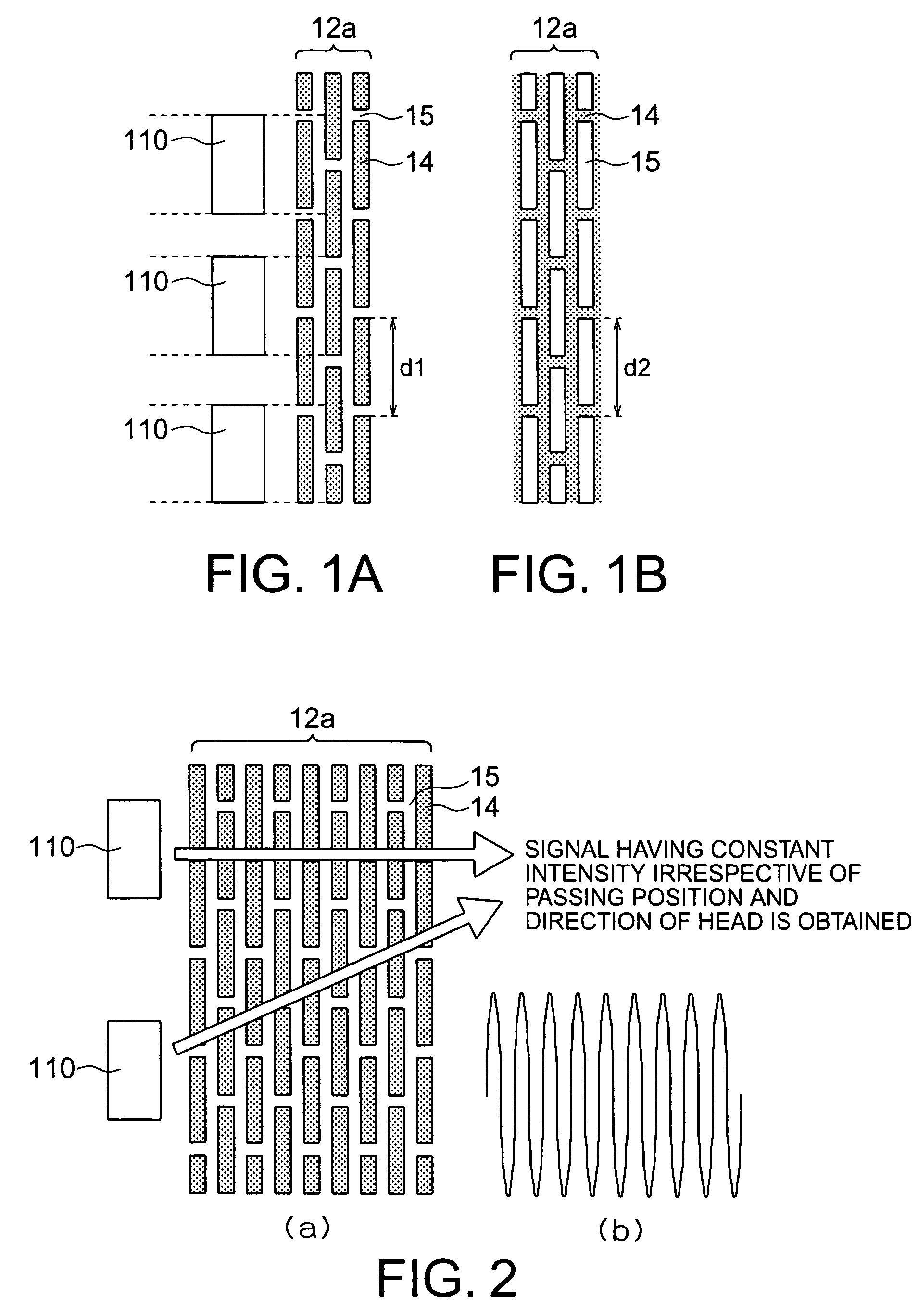
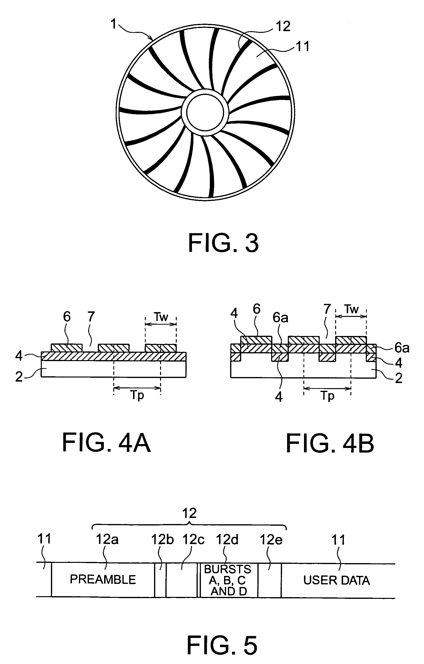
[0045]A magnetic disk medium according to a first embodiment of the present invention will now be described with reference to FIGS. 1A to 6. A magnetic disk medium according to the present embodiment is a patterned medium. Its schematic configuration is shown in FIGS. 3 to 5. FIG. 3 is a top view of a patterned medium 1. FIGS. 4A and 4B are sectional views obtained by cutting a data area of the patterned medium 1 along the radial direction. FIG. 5 is a diagram showing a servo area of the patterned medium 1.
[0046]As shown in FIG. 3, the patterned medium 1 includes a data area 11 and a servo area 12. The data area 11 is an area where user data are recorded. The data area 11 has a pattern in which tracks formed of magnetic materials formed in an annular form are arranged at periods of a definite length (track pitch Tp) via non-magnetic parts. The tracks formed of magnetic materials formed in the annular form are divided into sectors in the circumference direction by the servo area 12. ...
second embodiment
[0062]A magnetic disk medium according to a second embodiment of the present invention will now be described with reference to FIGS. 7A, 7B and 7C.
[0063]Typically in the magnetic recording and reproducing apparatuses, a recording and reproducing head attached to an arm moves on a magnetic disk medium to record and reproduce magnetic recording information on the magnetic disk medium. However, the relative angle between the track direction on the magnetic disk medium and the arm, i.e., the skew angle varies depending upon the position of the recording and reproducing head. In the first embodiment, strips in the recording patterns formed of the magnetic materials 14 in the preamble part 12a are divided periodically by the non-magnetic materials 15. The periodic interval of the division is nearly equal to the width of the reproducing head 110 irrespective of the skew angle. The present embodiment is configured so as to make the periodic interval of the recording patterns in the preamble...
third embodiment
[0069]A magnetic disk medium according to a third embodiment of the present invention will now be described with reference to FIG. 8. The magnetic disk medium according to the present embodiment is a patterned medium. As shown in FIG. 8, recording tracks 6 formed of magnetic materials in the data area are separated by non-magnetic materials 13. In parts between adjacent recording tracks 6 formed of magnetic materials, support parts 6b formed of magnetic materials are provided in the track width direction. In other words, adjacent recording tracks 6 are joined by the support parts 6b formed of the same magnetic material. The support parts 6b are shown to have the same height as the tracks 6. As a matter of fact, the support parts 6b may be made lower than the tracks 6. The non-magnetic material 13 is shown to have a non-magnetic material embedded therein and have the same height as that of the magnetic material parts 6 and the support parts 6b. As a matter of fact, the non-magnetic m...
PUM
| Property | Measurement | Unit |
|---|---|---|
| thickness | aaaaa | aaaaa |
| width | aaaaa | aaaaa |
| width | aaaaa | aaaaa |
Abstract
Description
Claims
Application Information
 - R&D
- Intellectual Property
- Life Sciences
- Materials
- Tech Scout
- Unparalleled Data Quality
- Higher Quality Content
- 60% Fewer Hallucinations
Browse by: Latest US Patents, China's latest patents, Technical Efficacy Thesaurus, Application Domain, Technology Topic, Popular Technical Reports.
© 2025 PatSnap. All rights reserved.Legal|Privacy policy|Modern Slavery Act Transparency Statement|Sitemap|About US| Contact US: help@patsnap.com


