Ultrasonic rotary-hammer drill

a rotary hammer drill and ultrasonic technology, applied in the field of drilling, can solve the problems of inability to operate continuously without loss of efficiency, limited drilling techniques, and limited application capabilities of existing rotary corers, etc., to achieve the effect of reducing the cost of drilling, and consuming low amounts of power/energy

Inactive Publication Date: 2010-06-22
NAT AERONAUTICS & SPACE ADMINISTATION U S GOVERNMENT AS REPRESENTED BY THE ADMINISTATOR OF THE
View PDF38 Cites 33 Cited by
  • Summary
  • Abstract
  • Description
  • Claims
  • Application Information

AI Technical Summary

Benefits of technology

[0017]It is still another object to provide hammering drills that are light weight and consume low amounts of power/energy.
[0018]In accordance with the foregoing objects, the present invention is an ultrasonic/sonic actuator-based hammering drill having a two-section drill bit including a fluted shaft leading to a distal crown cutter with teeth. The ultrasonic/sonic actuator comprises a piezoelectric stack connected to an ultrasonic transducer horn, wherein the piezoelectric stack is maintained in compression between a backing and the horn by a prestress bolt to form the ultrasonic/sonic actuator. Further, the ultrasonic/sonic actuator is in contact with a free mass and the drill bit. The piezoelectric stack creates vibrations that are amplified by the horn. As the horn strikes the free-mass, momentum is carried into the bit, creating sonic pulses. These pulses cause a percussion effect between the bit and the rock and the rock fractures when its ultimate strain is exceeded. The bit penetrates sampled media by repeated hammering action. In addition, in the preferred embodiment the bit is rotated. To achieve this, a key

Problems solved by technology

Existing drilling techniques are limited by the need for high axial forces, large power consumption, as well as a need to operate from a heavy platform to drill in non-horizontal and/or hard surfaces.
Accordingly, the capability of existing rotary corers has limited application in power and mass constrained environments.
Such drilling rigs cannot be duty cycled continuously without a loss of efficiency.
In addition, because the grinding mechanism is determined by the compression failure of the rock, the teeth of the corers must be re-sharpened frequently.
Accordingly, sharpness of the bits must be monitored otherwise t

Method used


Image

  • Ultrasonic rotary-hammer drill
  • Ultrasonic rotary-hammer drill
  • Ultrasonic rotary-hammer drill

Examples


Embodiment Construction

[0026]The present invention is a hammering drill based on an ultrasonic / sonic actuator that employs a unique drill bit and independent hammering actuator with rotary actuator for operation of the bit by a combination of hammering with rotation for increased penetration and cuttings removal efficiency.

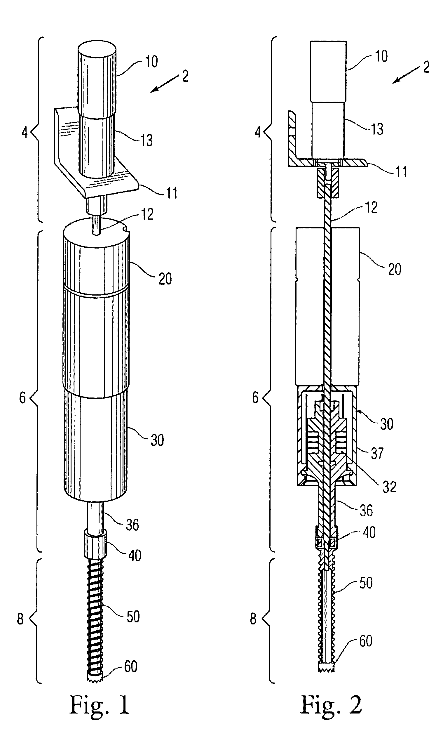
[0027]FIG. 1 is a perspective view of an exemplary embodiment of the hammering drill based on ultrasonic / sonic actuator 2 that generally includes three main sections: a rotary section 4; hammering ultrasonic / sonic actuator section 6; and drill bit 8.

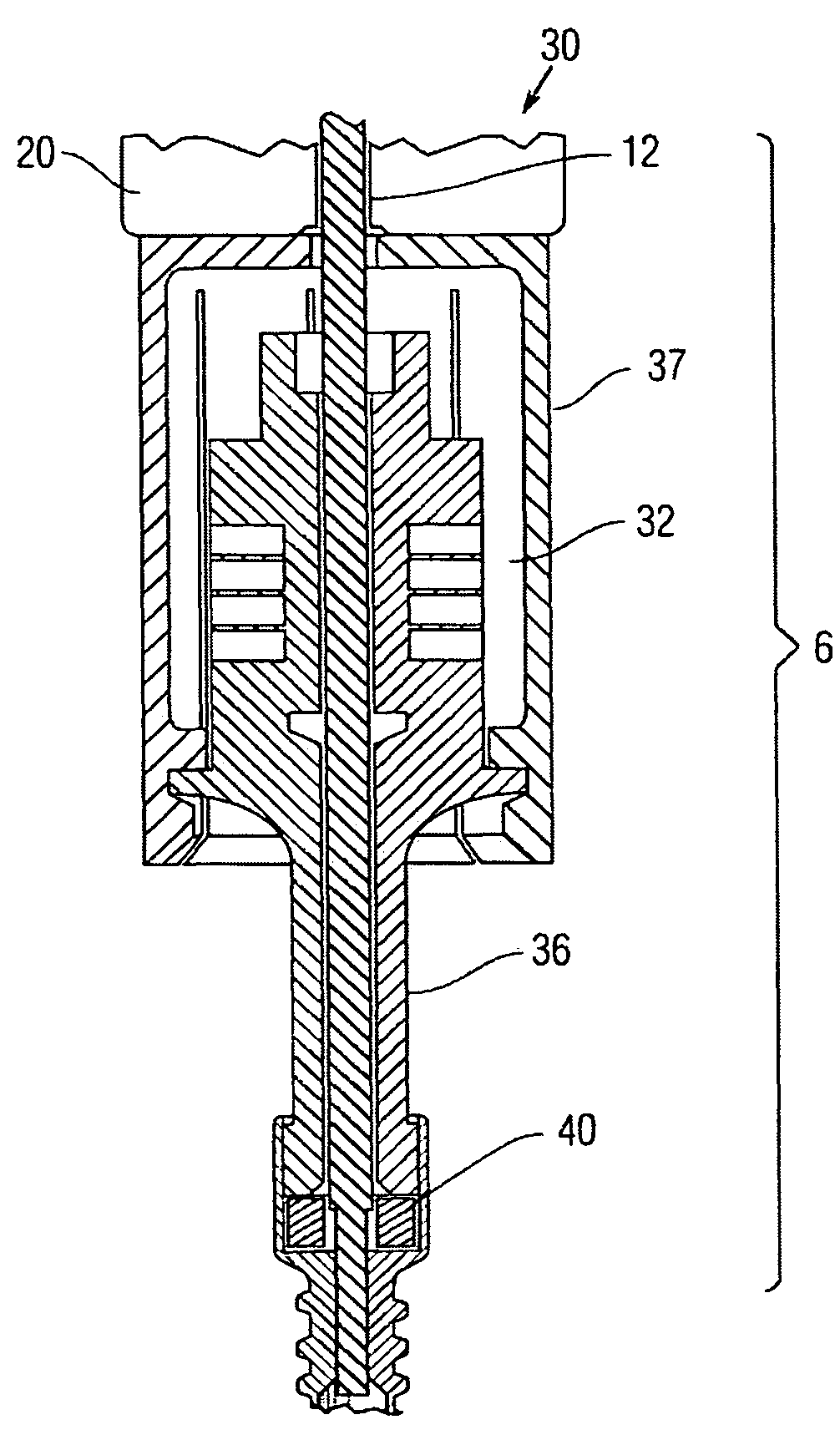
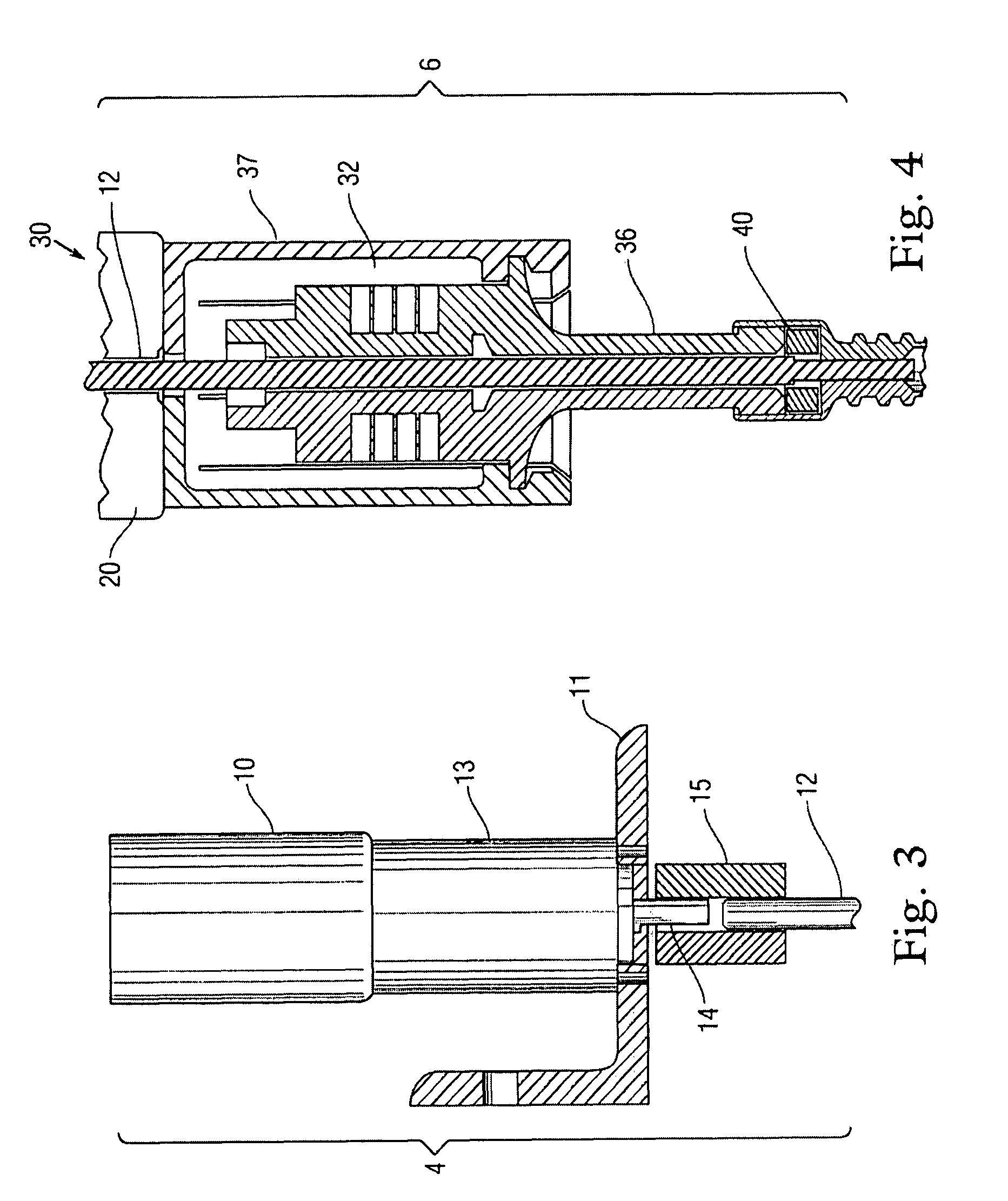
[0028]The hammering ultrasonic / sonic actuator section 6 further comprises a set of preload weights 20 mounted atop an ultrasonic / sonic actuator 30, the actuator 30 being connected via an ultrasonic transducer horn 36 to a free mass 40. The free mass 40 is sonically coupled to the drill bit 8.

[0029]The rotary section 4 further comprises a motor 10 mounted stationery on a bracket 11 or the like, the motor 10 being coupled through a drive shaft...


PUM


Abstract

A mechanism for drilling or coring by a combination of sonic hammering and rotation. The drill includes a hammering section with a set of preload weights mounted atop a hammering actuator and an axial passage through the hammering section. In addition, a rotary section includes a motor coupled to a drive shaft that traverses the axial passage through the hammering section. A drill bit is coupled to the drive shaft for drilling by a combination of sonic hammering and rotation. The drill bit includes a fluted shaft leading to a distal crown cutter with teeth. The bit penetrates sampled media by repeated hammering action. In addition, the bit is rotated. As it rotates the fluted bit carries powdered cuttings helically upward along the side of the bit to the surface.

Description

STATEMENT OF GOVERNMENT INTEREST[0001]The invention described hereunder was made in the performance of work under a NASA contract, and is subject to the provisions of Public Law #96-517 (35 U.S.C. 202) in which the Contractor has elected not to retain title.BACKGROUND OF THE INVENTION[0002]1. Field of the Invention[0003]The present invention generally relates to the field of drilling, and more particularly, relates to apparatus for penetrating, sampling, probing, and testing of a medium.[0004]2. Description of Prior Art[0005]Effective probing, drilling and coring apparatus find use in a great number of areas such as, for example, planetary exploration, military, medical operations, construction, police investigations, geology, archaeology sports (for example hiking and rock climbing) and other games.[0006]Existing drilling techniques are limited by the need for high axial forces, large power consumption, as well as a need to operate from a heavy platform to drill in non-horizontal a...

Claims


Application Information

Patent Timeline
IPC IPC(8): E21B10/36
CPCE21B7/24E21B6/08
Inventor BAR-COHEN, YOSEPHBADESCU, MIRCEASHERRIT, STEWARTBAO, XIAOQIKASSAB, STEVE
Owner NAT AERONAUTICS & SPACE ADMINISTATION U S GOVERNMENT AS REPRESENTED BY THE ADMINISTATOR OF THE
Why Eureka
Try Eureka