Self adjusting solenoid driver and method

a solenoid driver and self-adjusting technology, which is applied in the direction of liquid transfer devices, valve operating means/releasing devices, relays, etc., can solve the problems of degrading the performance of the fluid dispenser, the operation of the pneumatic solenoid is subject to less precise control, and the life of the solenoid is generally shorter than the electric on

Inactive Publication Date: 2010-06-22
NORDSON CORP
View PDF15 Cites 40 Cited by
  • Summary
  • Abstract
  • Description
  • Claims
  • Application Information

AI Technical Summary

Benefits of technology

[0012]In a further embodiment of the invention, a method is provided for operating a fluid dispenser that is controllable to dispense a fluid onto a substrate. The fluid dispenser has a dispensing valve movable between open and closed positions for controlling a flow of the fluid from the fluid dispenser. The fluid dispenser further has a solenoid with a coil in electromagnetic communication with an armature being movable through a displacement by energizing the coil. The operation of the solenoid is effective to cause the dispensing valve to move between the open and closed positions. The method comprises providing a power supply having a voltage and producing an output drive signal having a time variable component determined as a function of the voltage of the power supply. That output signal is applied to the coil of the solenoid, thereby automatically changing the operation of the dispensing valve as a function of the voltage of the power supply.

Problems solved by technology

However, pneumatic solenoids have disadvantages in that they generally have a shorter life than electric solenoids, and the operation of the pneumatic solenoid is subject to less precise control than the electric solenoid in an electric fluid dispenser.
However, simply doubling the applied voltage without other changes to the solenoid driver circuit would cause overheating and possibly degrade the performance of the fluid dispenser.
However, the low voltage solenoid driver provides an initial current pulse having more power than is required by the solenoid which results in an inefficient operation of the coil.
The requirement of replacing the whole driver circuit to upgrade the performance of the fluid dispenser is labor intensive, time consuming and expensive.
While the above problem has been described with respect to an electrically operated fluid dispenser, a similar problem exists with respect to pneumatically operated fluid dispensers.

Method used


Image

  • Self adjusting solenoid driver and method
  • Self adjusting solenoid driver and method
  • Self adjusting solenoid driver and method

Examples


Embodiment Construction

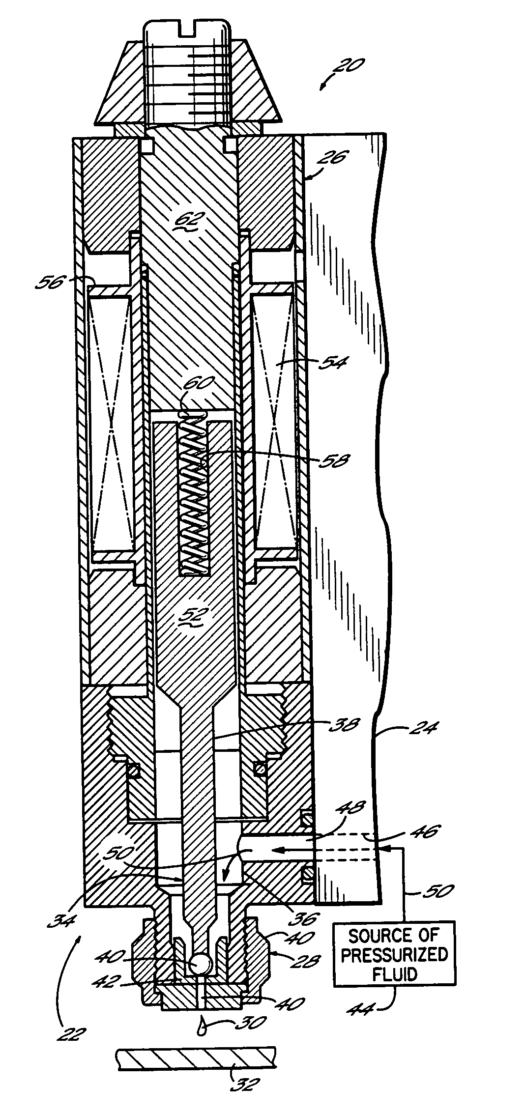
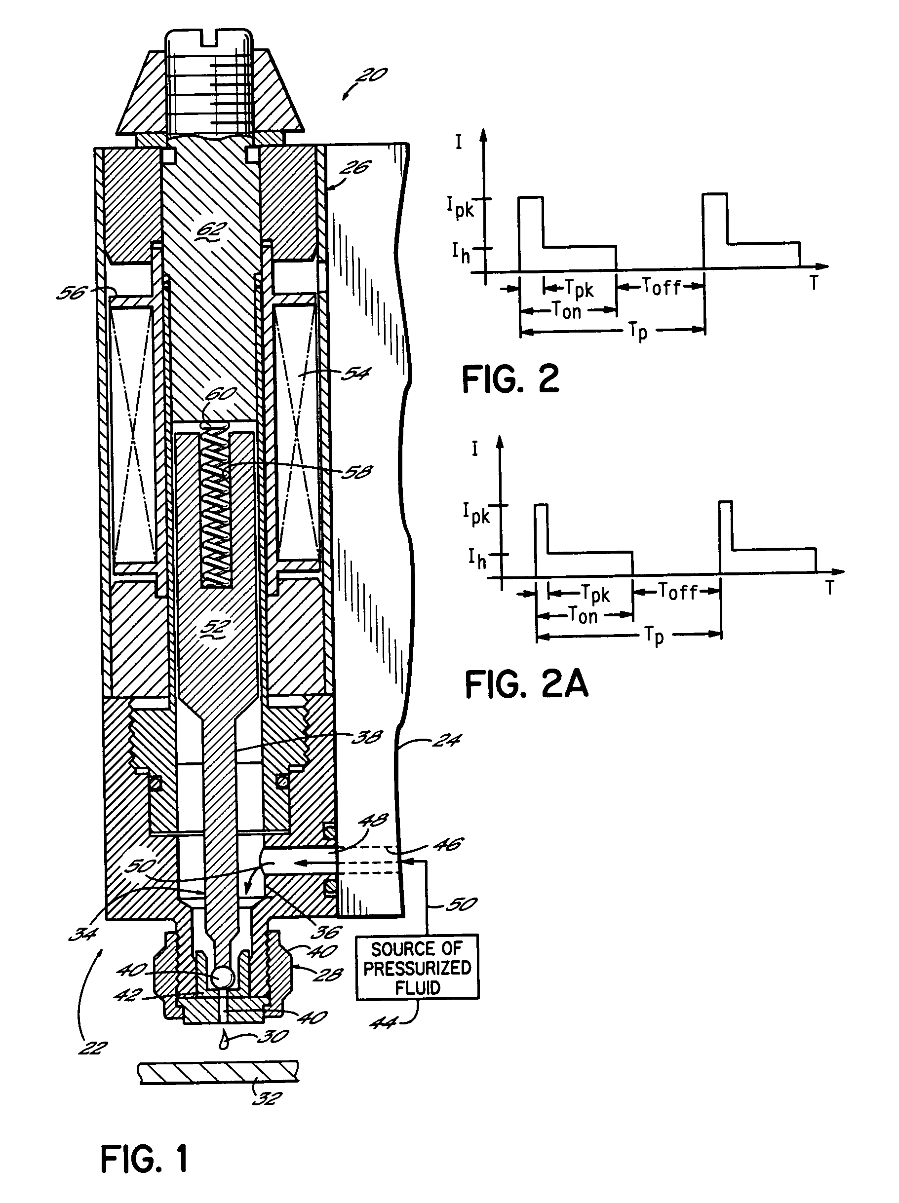
[0021]Referring to FIG. 1, an electrically operated fluid dispenser or dispensing gun 20 comprises one or more dispensing modules or valves 22 mounted on a fluid distribution manifold plate 24 in a known manner. The dispensing valve 22 includes a dispenser body 26 and a fluid dispensing nozzle body 28. The dispenser 20 normally used to dispense high viscosity fluids, for example, a hot melt adhesive, solder flux, thermal grease, etc., but low viscosity fluids can benefit from the invention as well. Furthermore, the dispenser 20 is mounted in a dispensing machine or system (not shown) in a known manner to dispense fluids in discrete amounts, for example, as droplets or dots, but alternatively in continuous beads. As shown in FIG. 1, the dispenser body 26 used in conjunction with the fluid dispensing nozzle body 28 is particularly constructed to dispense fluid 30 onto a substrate 32. Relative motion between the substrate 32 and dispenser 20 is provided in a known manner.

[0022]A valve ...


PUM

PropertyMeasurementUnit
output voltageaaaaaaaaaa
voltageaaaaaaaaaa

Abstract

A fluid dispenser having a dispensing valve movable between open and closed positions for controlling the flow of the fluid from the fluid dispenser. A solenoid is operatively connected to the dispensing valve and is capable of moving the dispensing valve between the open and closed positions. The fluid dispenser further includes a power supply having a voltage and a driver circuit electrically connected to the solenoid and the power supply. The driver circuit provides an output signal to the solenoid having a time variable component, for example, a peak current duration, determined as a function of the voltage of the power supply. Thus, the driver circuit automatically adjusts to, and can be used with, power supplies of different voltages. The invention further includes a method by which the driver circuit provides the output signal as a function of the power supply voltage.

Description

FIELD OF THE INVENTION[0001]The present invention generally relates to an apparatus for dispensing fluids and more specifically, to an improved gun driver circuit of a fluid dispensing apparatus.BACKGROUND OF THE INVENTION[0002]Pneumatic and electric fluid dispensers have been developed for dispensing applications requiring a precise placement of a fluid. Pneumatic dispensers have a significant advantage in that the pneumatic solenoid operating the dispensing valve provides a sufficient force so that the dispensing valve operation is essentially independent of the viscosity of the fluid being dispensed. However, pneumatic solenoids have disadvantages in that they generally have a shorter life than electric solenoids, and the operation of the pneumatic solenoid is subject to less precise control than the electric solenoid in an electric fluid dispenser. Therefore, in some applications, electrically operated fluid dispensers are preferred over pneumatic fluid dispensers.[0003]Generall...

Claims


Application Information

Patent Timeline
Patent Type & Authority Patents(United States)
IPC IPC(8): F16K31/02B67D7/08F16K31/06H01F7/18
CPCF16K31/0665B05B1/3053
Inventor ESTELLE, PETER W.
Owner NORDSON CORP
Why Eureka
Try Eureka