Fastener

a fastener and head section technology, applied in the field of fasteners, can solve the problems of the abovementioned fastener, the risk of the dielectric cap peeling off (coming off) from the head section of the fastener, and the obstruction of the flow of electric shock current, so as to prevent damage

Inactive Publication Date: 2010-06-22
MITSUBISHI HEAVY IND LTD
View PDF14 Cites 22 Cited by
  • Summary
  • Abstract
  • Description
  • Claims
  • Application Information

AI Technical Summary

Benefits of technology

[0007]In consideration of the above described problems, an object of the present invention is to provide a fastener able to prevent damage due to environmental factors such as ultraviolet rays, and impact from sanddust, without obstructing a flow of electric shock current that flows along a top surface of an outer plate.
[0008]Moreover, another object of the present invention is to provide a lightning protection fastener in which any possibility of peeling off during operation of an aircraft is eliminated.

Problems solved by technology

In the fastener disclosed in the above Patent Document, the dielectric cap is positioned on the top surface of the aircraft, so that, in the case of guiding electric shock current of lightning along the top surface of the outer skin, there is a problem that the electric shock current needs to flow around this dielectric cap and the flow of electric shock current is obstructed.
Moreover, from the point of view of Lightning Protection Redundancy required by section 25.981(a)(3) of the FAR (Federal Aviation Regulation) of the United States of America, the abovementioned fastener is not appropriate because of a lack of sufficient countermeasures against deterioration of the dielectric cap due to environmental factors such as ultraviolet rays and damage due to impact from sanddust, lumps of ice and raindrops.
Furthermore there is a risk of the dielectric caps peeling off (coming off) from the head section of the fastener during operation of the aircraft.

Method used


Image

  • Fastener
  • Fastener
  • Fastener

Examples


first embodiment

[0035]Hereinafter, a lightning protection fastener according to present invention is described, with reference to the drawings.

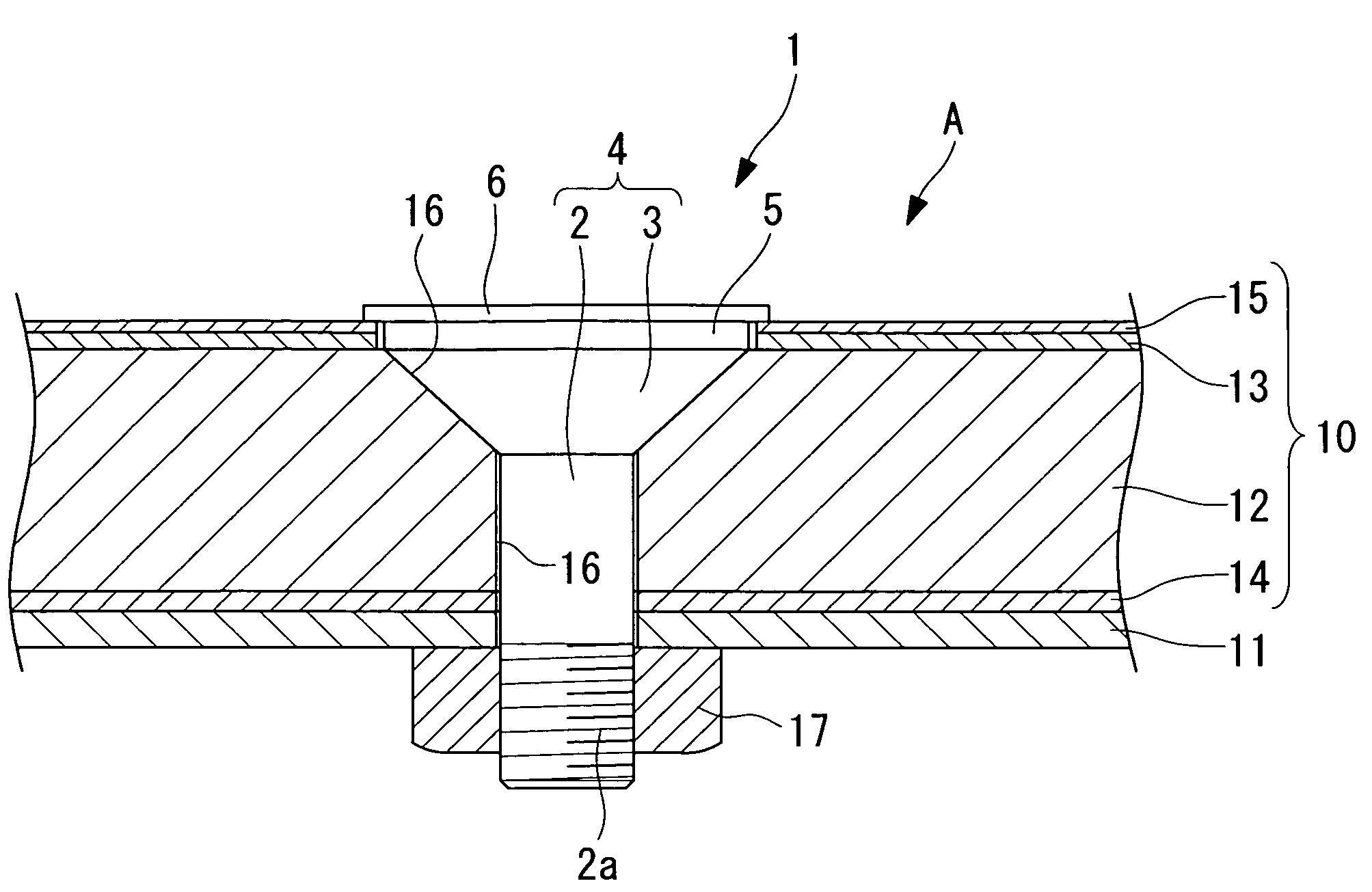
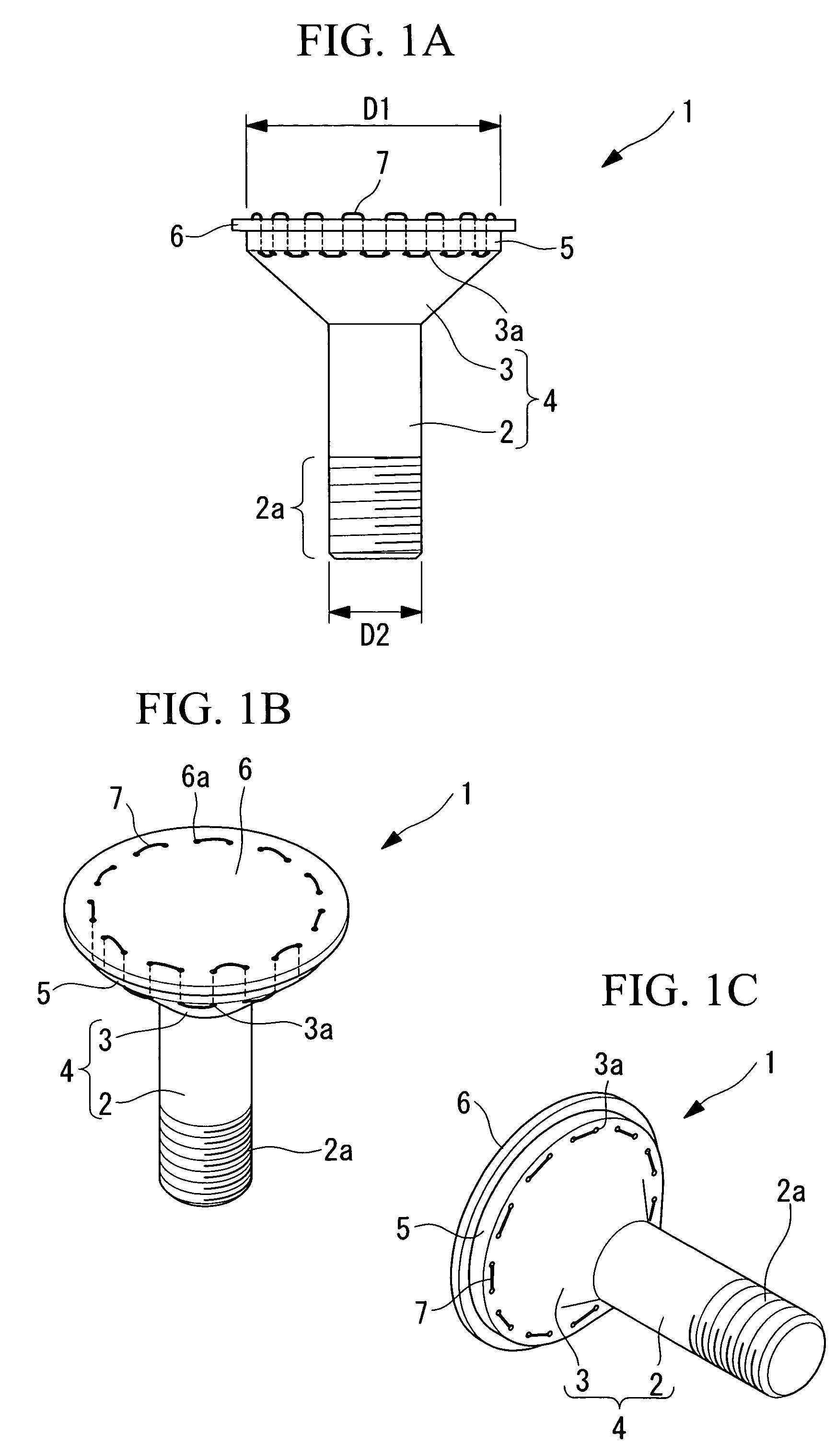
[0036]As shown in FIG. 1, the lightning protection fastener (hereinafter, referred to as the “fastener”) 1 according to the present embodiment comprises as the main components: a fastener main body 4 having a column shaped shank section (Shank) 2 and a substantially conically shaped head section (Flush Head) 3 the diameter of which becomes greater in the direction away from the shank section 2; a dielectric layer 5 arranged to cover one end surface (upper side end surface in FIG. 1(a)) of the head section 3; a conductive layer 6 arranged to cover one end surface (upper side end surface in FIG. 1(a)) of the dielectric layer 5; and a fixing means 7.

[0037]The fastener main body 4 is formed from the integration of the shank section 2 and the head section 3, and is fabricated using alloy metals such as titanium (Ti-6Al-4V: annealed material) and inconel, for exam...

second embodiment

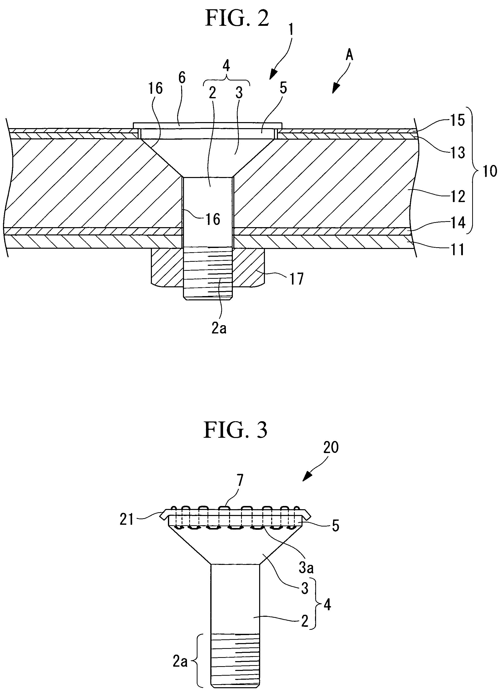
[0060]A second embodiment according to the present invention is described, using FIG. 3.

[0061]A fastener 20 in the present embodiment differs from the above described embodiment in that a conductive layer 21 is provided instead of the conductive layer 6 described above, in which a circumference section positioned to the outside of the through holes 6a in a radial direction is bent towards (made to face) the fastener main body 4 side (downside in FIG. 3). Other components are identical with those in the first embodiment described above, and descriptions for these identical components are omitted here.

[0062]Moreover, the same reference symbols are given to members that are identical with those in the first embodiment.

[0063]According to the fastener 20 of the present embodiment, in the case where it is used for connecting the outer skin 10 to a structural member 11 (for example, a rib or a stringer) of an aircraft as shown in FIG. 2 for example, since a back surface positioned on the c...

third embodiment

[0065]A third embodiment according to the present invention is described, using FIG. 4.

[0066]A fastener 30 in the present embodiment differs from the first embodiment in that a double layer structure 31 in which a conductive layer 6 is laminated on the top surface of a dielectric layer 5, is fixed on (attached to) the head section 3 of the fastener main body 4 via an adhesive agent (not shown in the diagram) . Other components are identical with those in the first embodiment described above, and descriptions for these identical components are omitted here.

[0067]Moreover, the same reference symbols are given to members that are identical with those in the first embodiment.

[0068]In the present embodiment, GFRP having a thickness of 1.0 mm is used as the dielectric layer 5, and copper foil having a thickness of 0.2 mm (a thickness of 30 μm may even be used) is used as the conductive layer 6.

[0069]Moreover, epoxy adhesive agent (for example, the epoxy adhesive agent EA9396 made by the c...


PUM


Abstract

There is provided a fastener able to prevent damage due to environmental factors such as ultraviolet rays, and impact from sanddust, lumps of ice, and raindrops without obstructing a flow of electric shock current that flows along a top surface of an outer skin. The fastener connects an outer skin of an aircraft to a structural member positioned inside this outer skin, and is provided with a dielectric layer arranged to cover one end surface of a head section, and a conductive layer arranged to cover one end surface of this dielectric layer.

Description

BACKGROUND OF THE INVENTION[0001]1. Field of the Invention[0002]The present invention relates to a fastener used where an electric conductive plastic material (for example, CFRP (carbon fiber reinforced plastic)) is used as an outer skin of an aircraft, and, in particular, to a lightning protection fastener.[0003]2. Description of the Related Art[0004]As a fastener used when an electric conductive plastic material is used as an outer skin of an aircraft, a fastener disclosed in the Specification of U.S. Pat. No. 4,630,168 is known, in which one end surface of a head section is covered by a dielectric cap.[0005]In the fastener disclosed in the above Patent Document, the dielectric cap is positioned on the top surface of the aircraft, so that, in the case of guiding electric shock current of lightning along the top surface of the outer skin, there is a problem that the electric shock current needs to flow around this dielectric cap and the flow of electric shock current is obstructed....

Claims


Application Information

Patent Timeline
Patent Type & Authority Patents(United States)
IPC IPC(8): F16B37/14B64D45/02
CPCB64D45/02F16B37/14F16B35/06F16B11/00F16B2001/0064F16B2200/93
Inventor KAMINO, YUICHIROOGURI, KAZUYUKISENDA, MAKOTOSEKIGAWA, TAKAHIROINOUE, AKIKO
Owner MITSUBISHI HEAVY IND LTD
Why Eureka
Try Eureka