Method for forming a carbon nanotube aggregate

a carbon nanotube and aggregate technology, applied in the field of carbon nanotube aggregate, can solve the problems of not being able to use the excellent physical property of carbon nanotube in a macro state, and the problem of obtaining the aggregate of carbon nanotubes

Inactive Publication Date: 2010-06-22
STELLA CHEMIFA CORP
View PDF3 Cites 29 Cited by
  • Summary
  • Abstract
  • Description
  • Claims
  • Application Information

AI Technical Summary

Benefits of technology

[0018]As described above, the present invention is composed of a step of fluorinating and a step of sintering fluorinated multiple carbon nanotubes, and enables to form the aggregate of carbon nanotubes alone. The carbon nanotube aggregate is composed of the carbon nanotubes alone, and has possibility for various fields because of being constructed as those combining its properties.

Problems solved by technology

The addition of the carbon nanotube adamantly aims at enhancing the physical property of the matrix, and does not enable to use the excellent physical property of the carbon nanotube in a macro state.
Thus, it has been made a problem to obtain the aggregate of the carbon nanotubes, which was not carried out in the above prior publications.

Method used


Image

  • Method for forming a carbon nanotube aggregate
  • Method for forming a carbon nanotube aggregate
  • Method for forming a carbon nanotube aggregate

Examples


example 1

Purification of Carbon Nanotubes

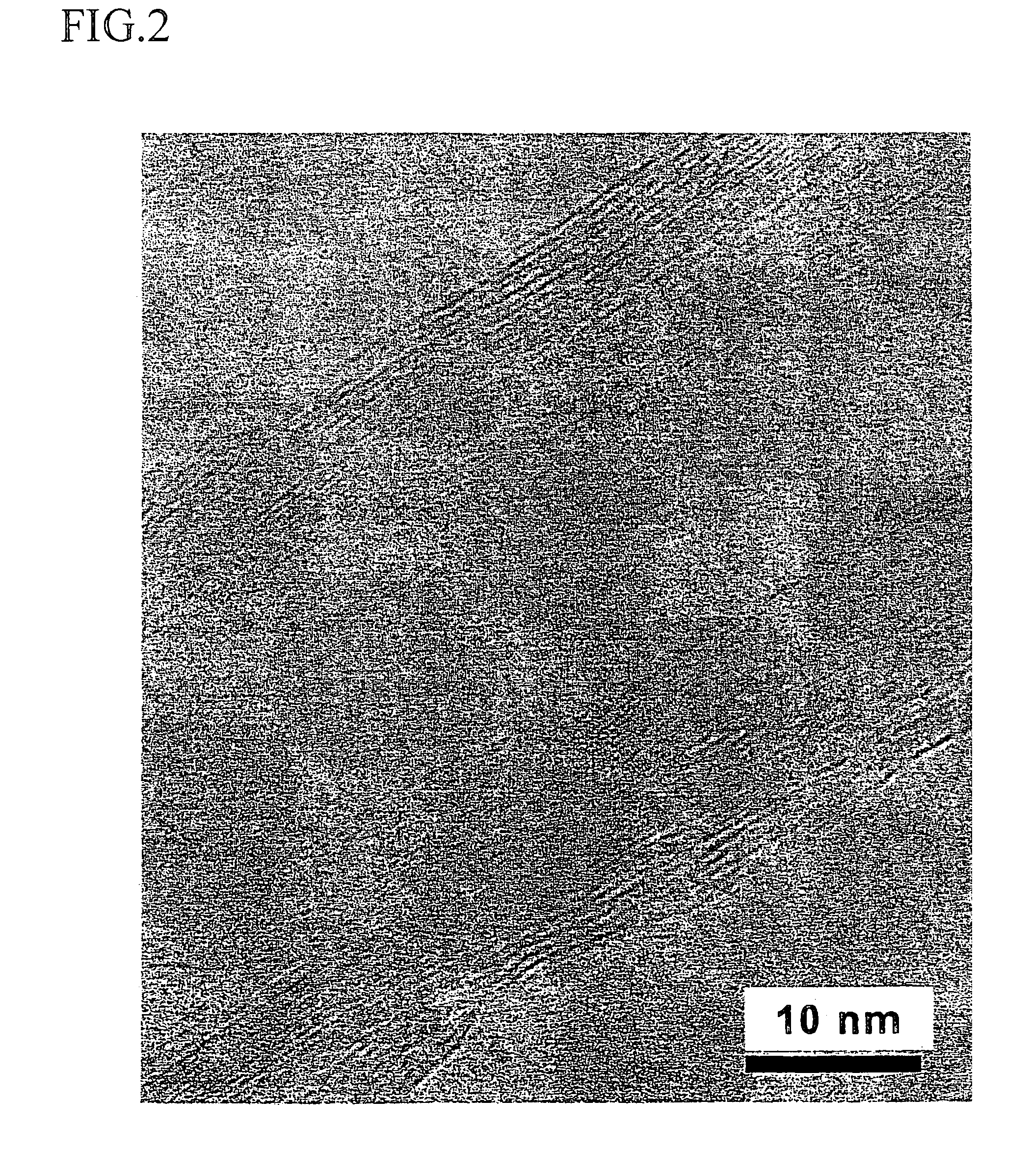
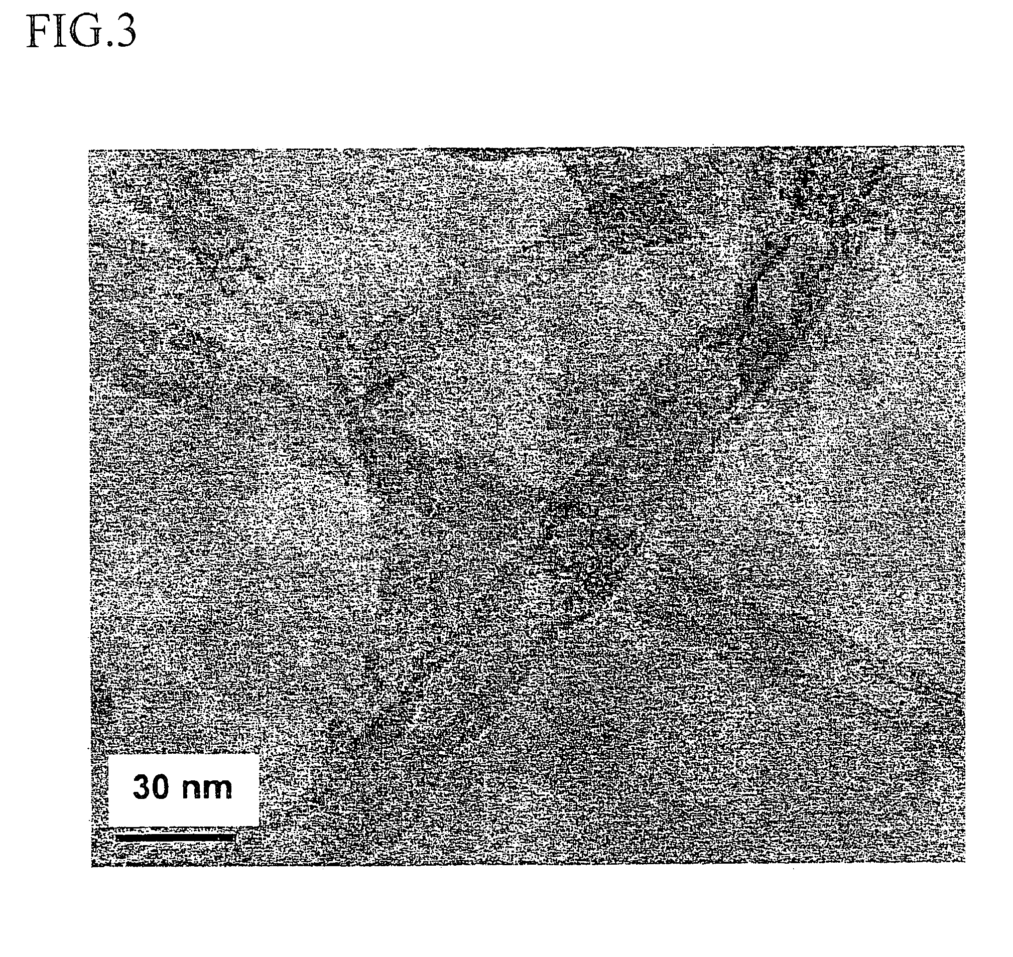
[0048]Unpurified multilayer carbon nanotubes (100 mg) is fired and oxidized at 500° C. for 90 minutes in air. Subsequently, the oxidized sample (1 g) is placed in 6 M HCl (1 L) and left stand in an oven at 60° C. for 12 hours or more. Then, 500 mg of the filtrated and dried sample was placed in 2 M NaOH (500 mL) and refluxed for 6 hours. NaOH is removed by rinsing with hot water with filtrating. A filter residue was dried in the oven at 60° C. When confirmed using TEM, SEM and X ray photoelectron spectrometry, the filter residue was the purified multilayer carbon nanotubes from which amorphous carbon and the catalytic metal had been removed.

example 2

Investigation of Fluorination Container

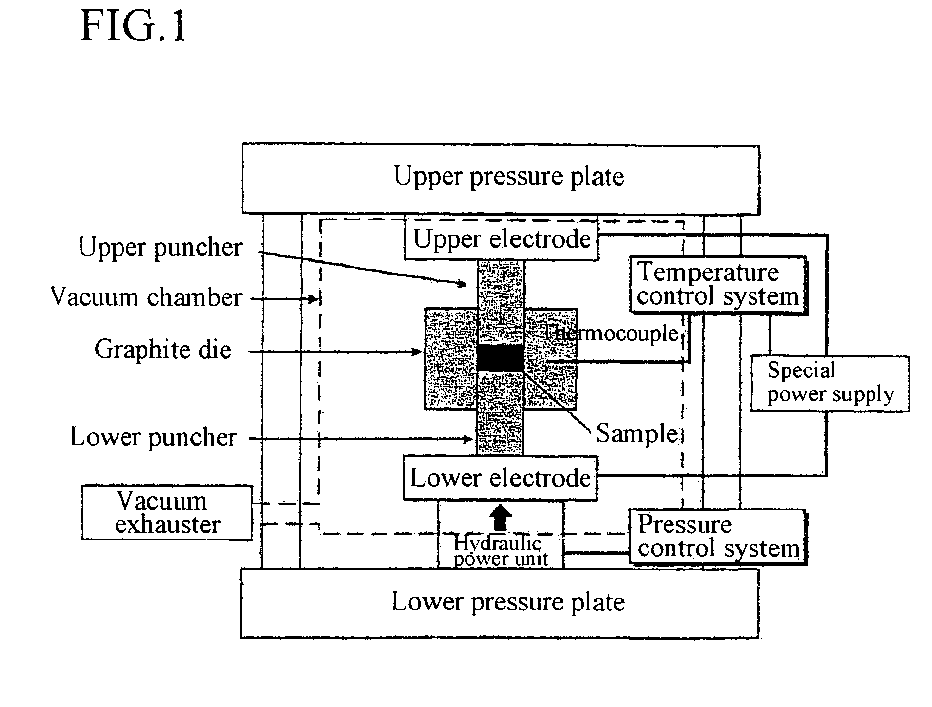
[0049]The carbon nanotubes (100 mg) purified in Example 1 are collected in each container (5 mL) of SUS316L, nickel (Ni), platinum (Pt) or polytetrafluoroethylene (PTFE), and the container is set in a chamber (30 mL) made from SUS316L to which electrolytic polish was given. Subsequently, vacuum replacement with nitrogen is performed in the chamber, and the temperature is raised to 250° C. at 2° C. / minute under nitrogen flow (20 cc / minute) to perform a constant temperature treatment for 6 hours. After cooling, the vacuum replacement with 20% fluorine (F2) gas diluted with nitrogen is performed, and 20% F2 is run at 25 cc / minute. Then, the chamber was heated to the given temperature at 8° C. / minute and the temperature was kept for 9 hours to flourinate. As a result, in the case of using the PTFE container, the good fluorination was performed without undergoing metallic contamination.

[0050]Table 1 shows the presence or absence of the metallic cont...

example 3

Fluorinated Carbon Nanotubes

[0052]The multilayer carbon nanotubes (500 mg) purified in Example 1 are collected in the PTFE container (5 mL), and the container is set in the chamber (30 mL) made from SUS316L to which electrolytic polish was given. Subsequently, the vacuum replacement with nitrogen is performed in the chamber, and the temperature is raised to 250° C. at 2° C. / minute under nitrogen flow (20 cc / minute) to perform the constant temperature treatment for 6 hours. After cooling, the vacuum replacement with 20% fluorine (F2) gas diluted with nitrogen is performed, and 20% F2 is run at 25 cc / minute. Then, the chamber was heated to 250° C. at 8° C. / minute and the constant temperature treatment was performed for 9 hours.

[0053]The C—F bond in the treated multilayer carbon nanotubes was identified using the infrared spectrometer and the X ray photoelectron spectrometer. A peak in the vicinity of 1192.3 and a peak of C 1s289.5 eV (the charge was compensated by making unmodified ca...


PUM

PropertyMeasurementUnit
temperatureaaaaaaaaaa
pressureaaaaaaaaaa
diameteraaaaaaaaaa

Abstract

A carbon nanotube aggregate and a method for forming a carbon nanotube aggregate are provided. The carbon nanotube aggregate can be formed by treating carbon nanotubes with fluorine gas and sintering the resulting fluorinated carbon nanotubes. A carbon nanotube aggregate can be formed which does not contain a binder or resin matrix.

Description

TECHNICAL FIELD[0001]The present invention relates to an aggregate of carbon nanotubes in which the carbon nanotubes alone can constitute the aggregate, and which is practically applied for various fields such as thermal conductive materials and high strength materials as well as electronic materials and nanotechnology materials by taking advantage of its geometric and physicochemical characteristics.BACKGROUND ART[0002]In recent years, the nanotechnology has been highlighted and the carbon nanotube has attracted the attention of various fields. Development of practical application to probes, micromachines, conductive materials, thermal conductive materials, fuel batteries and solar batteries or many interesting uses for hydrogen storage materials has been actively-studied by taking advantage of specific functions of the carbon nanotubes. Conventionally, formed articles of carbon materials are accomplished by using resins, rubbers, thermoplastic elastomers, adhesives, paints, inks, ...

Claims


Application Information

Patent Timeline
Patent Type & Authority Patents(United States)
IPC IPC(8): D01F9/12A61K6/00A61L27/08A61L31/00B82B3/00C01B31/02H01M4/58H01M4/587H01M4/96
CPCA61L27/08B82Y30/00B82Y40/00C01B31/0253C01B31/026C04B35/83H01M4/587H01M4/96Y02E60/50C01B2202/06C04B2235/445C04B2235/5288C04B2235/6562C04B2235/6567C04B2235/666C04B2235/77C04B2235/96A61L2400/12C01B32/168C01B32/17H01G11/36H01G11/86Y02E60/10
Inventor TOHJI, KAZUYUKISATOH, YOSHINORIKIKUYAMA, HIROHISAWAKI, MASAHIDEHASHIGUCHI, SHINJITASHIRO, YASUTAKA
Owner STELLA CHEMIFA CORP
Why Eureka
Try Eureka