Phase contrast electron microscope

a phase contrast and electron microscope technology, applied in the field of phase contrast electron microscopes, can solve the problems of higher diffraction orders, difficult to achieve phase contrast, so as to achieve no deterioration of resolution, the effect of reducing the dimension requirement of the phase-shifting element and ensuring the effect of reducing the size of the beam

Active Publication Date: 2010-06-22
CARL ZEISS SMT GMBH
View PDF19 Cites 17 Cited by
  • Summary
  • Abstract
  • Description
  • Claims
  • Application Information

AI Technical Summary

Benefits of technology

[0007]It is an object of the invention to provide a phase contrast electron microscope wherein the dimensional requirements on the phase-shifting element are reduced. Another object of the invention is to avoid information loss in a phase contrast electron microscope.
[0012]The diffraction plane of the objective is imaged magnified into a diffraction intermediate image plane. For this reason, the phase-shifting element can be configured to be correspondingly geometrically larger so that the dimensional requirements imposed on the phase-shifting element are correspondingly reduced. At the same time, the blanking out of electrons with the hardware of the phase plate, especially electrodes and support elements, is reduced because the dimensions of these parts can remain the same. Furthermore, it can simultaneously be ensured that no deterioration of resolution occurs because of the aberrations of the additional diffraction lenses and the image of the diffraction plane behind the system of the diffraction lenses can lie clearly rearward of the image planes which are conjugated to the object plane of the objective.
[0013]Because, according to the first aspect of the invention, the principal plane of the second diffraction lens lies in or near the diffraction intermediate image plane, the second diffraction lens has an almost exclusive influence on the position of the image plane, which is conjugated to the object plane of the objective, and virtually no influence on the additional imaging of the diffraction intermediate image plane. The required structural length increase can thereby be kept low.

Problems solved by technology

However, the dimensions required in a transmission electron microscope are problematic.
The first starting point has the disadvantage that the small electrostatic lens perforce requires outer holding structures which interrupt regions wherein the paths of the electrons run which are diffracted into high diffraction orders whereby important information is lost for the generation of images.
With respect to the latter, the second starting point has the disadvantage that the higher orders of diffraction, which are anyway very weak compared to the unscattered ray, are additionally weakened by the unavoidable material absorption of the foil.

Method used


Image

  • Phase contrast electron microscope
  • Phase contrast electron microscope
  • Phase contrast electron microscope

Examples


Embodiment Construction

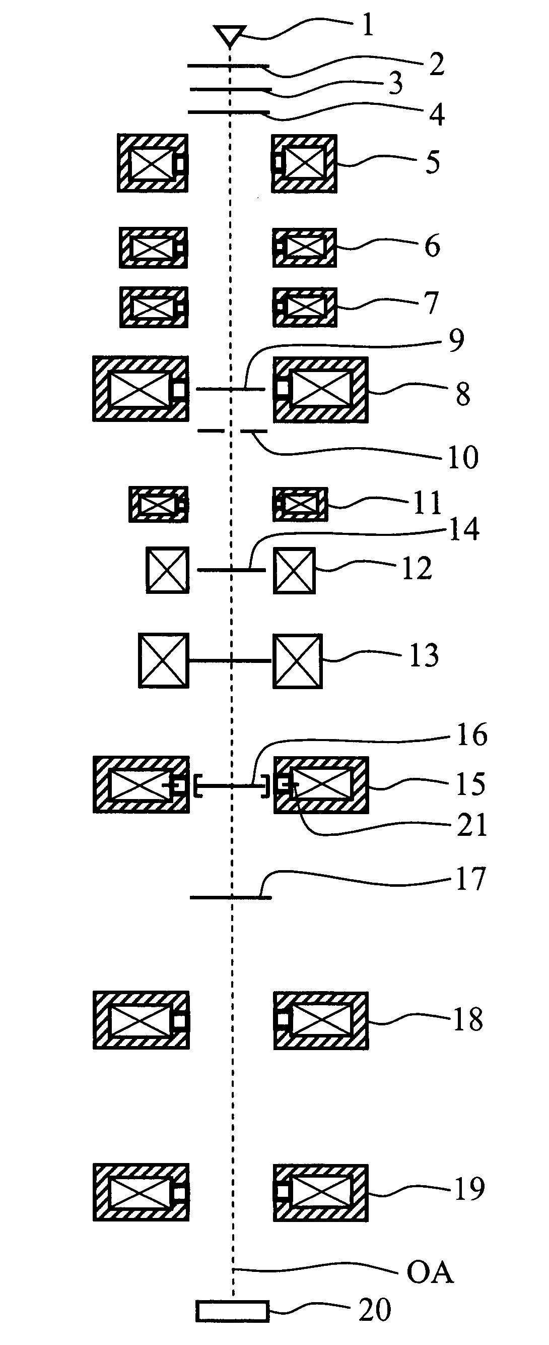
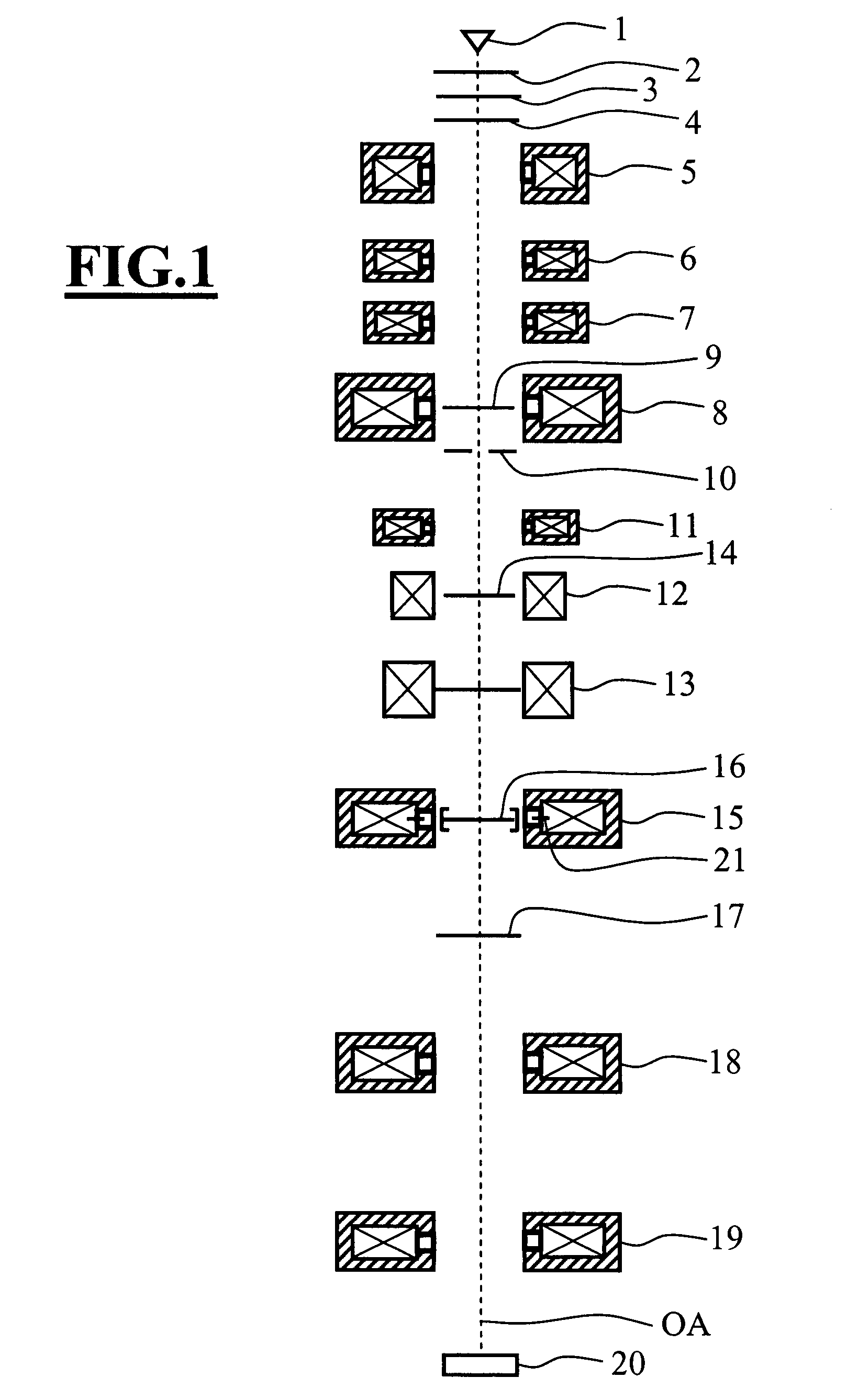
[0022]The transmission electron microscope of FIG. 1 includes an electron source 1, for example, a thermal field emission source. An extraction electrode 2 follows the electron source 1 and this extraction electrode has a potential which draws electrons from the electron source 1. The extraction electrode 2 is followed by one or several focusing electrodes 3 in order to optically fix the location of the source position and one or several anodes 4. Because of the potential of the anode 4, the electrons, which emanate from the electron source 1, are accelerated to the desired electron energy of 100 keV or more.

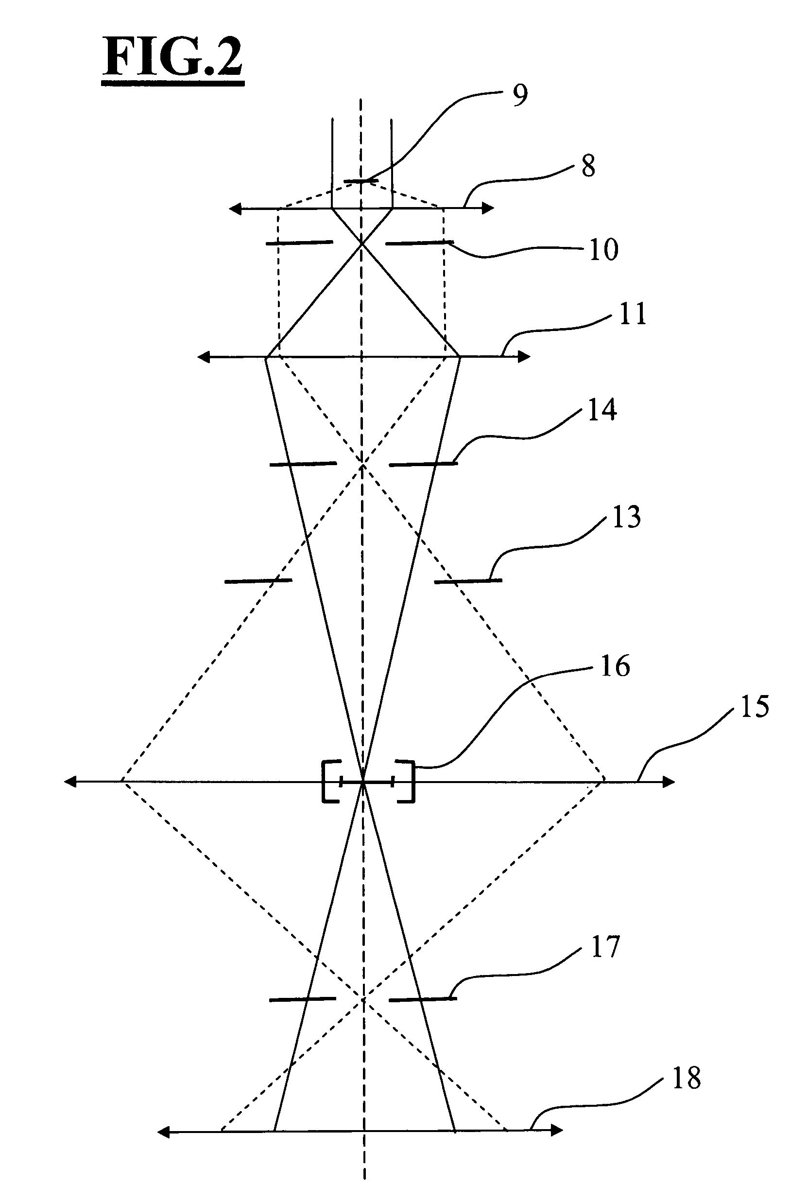
[0023]A multi-stage condenser follows the anode in the direction of movement of the electrons. In the embodiment shown, the condenser has three individual magnet lenses (5, 6, 7) and the entrance end part of the condenser-objective single-field lens 8. With a condenser of this kind, the illumination aperture as well as the field of the object plane 9 can be independently adjuste...


PUM

PropertyMeasurementUnit
diameteraaaaaaaaaa
focal lengthaaaaaaaaaa

Abstract

A phase contrast electron microscope has an objective (8) with a back focal plane (10), a first diffraction lens (11), which images the back focal plane (10) of the objective (8) magnified into a diffraction intermediate image plane, a second diffraction lens (15) whose principal plane is mounted in the proximity of the diffraction intermediate image plane and a phase-shifting element (16) which is mounted in or in the proximity of the diffraction intermediate image plane. Also, a phase contrast electron microscope has an objective (8) having a back focal plane (10), a first diffraction lens (11), a first phase-shifting element and a second phase-shifting element which is mounted in or in the proximity of the diffraction intermediate image plane. The first diffraction lens (11) images the back focal plane of the objective magnified into a diffraction intermediate image plane and the first phase-shifting element is mounted in the back focal plane (10) of the objective (8). With the magnified imaging of the diffraction plane by the diffraction lens, the dimensional requirements imposed on the phase plate having the phase-shifting element are reduced.

Description

CROSS REFERENCE TO RELATED APPLICATION[0001]This application claims priority of German patent application no. 10 2006 011 615.1, filed Mar. 14, 2006, the entire content of which is incorporated herein by reference.FIELD OF THE INVENTION[0002]The invention relates to a phase contrast electron microscope and especially a phase contrast transmission electron microscope.BACKGROUND OF THE INVENTION[0003]Electron microscope specimens are, as a rule, phase objects which generate only a very slight amplitude contrast in a transmission electron microscope because of the high electron energy in the range of 100 keV and higher. For this reason, in a conventional transmission electron microscope, objects of this kind generate a contrast only when utilizing the phase-shifting effect of the spherical aberration of the transmission electron microscope and are therefore imaged with correspondingly little contrast in a conventional transmission electron microscope. The introduction of a phase plate ...

Claims


Application Information

Patent Timeline
Patent Type & Authority Patents(United States)
IPC IPC(8): G01N23/00
CPCG01N23/04H01J37/04H01J37/26H01J2237/2614H01J2237/0492G01N23/041
Inventor BENNER, GERDMATIJEVIC, MARKO
Owner CARL ZEISS SMT GMBH
Why Eureka
Try Eureka