High energy crystal generators and their applications

a generator and high energy technology, applied in the field of high energy crystal generators and their applications, can solve problems such as large electrostatic field, and achieve the effect of reducing the number of pyroelectric and piezoelectric generators, and improving the efficiency of electrostatic fusors

Inactive Publication Date: 2010-06-22
RGT UNIV OF CALIFORNIA
View PDF9 Cites 20 Cited by
  • Summary
  • Abstract
  • Description
  • Claims
  • Application Information

AI Technical Summary

Benefits of technology

[0011]The crystal generator may be used as the source of energy in a wide variety of systems where a localized or compact beam of high energy ions or electrons is needed. Such systems include fusion, electron / ion emission driven by coercive field or acoustic stress or heating, therapeutic X-ray / electron devices, elemental analysis systems, localization of emission, local scanning chemical analysis, high energy scanning microscopy, point source compact transmission electron microscopy, compact ion beam sources, positron sources, micro-thrusters for ion engines, and as a way to get finer and pixilated and increased efficiency of electrostatic fusors of the Farnsworth type. And as front end deuterium ion beam sources for API [associated particle imaging].

Problems solved by technology

A modest change in temperature can lead to a large electrostatic field.

Method used


Image

  • High energy crystal generators and their applications
  • High energy crystal generators and their applications
  • High energy crystal generators and their applications

Examples


Embodiment Construction

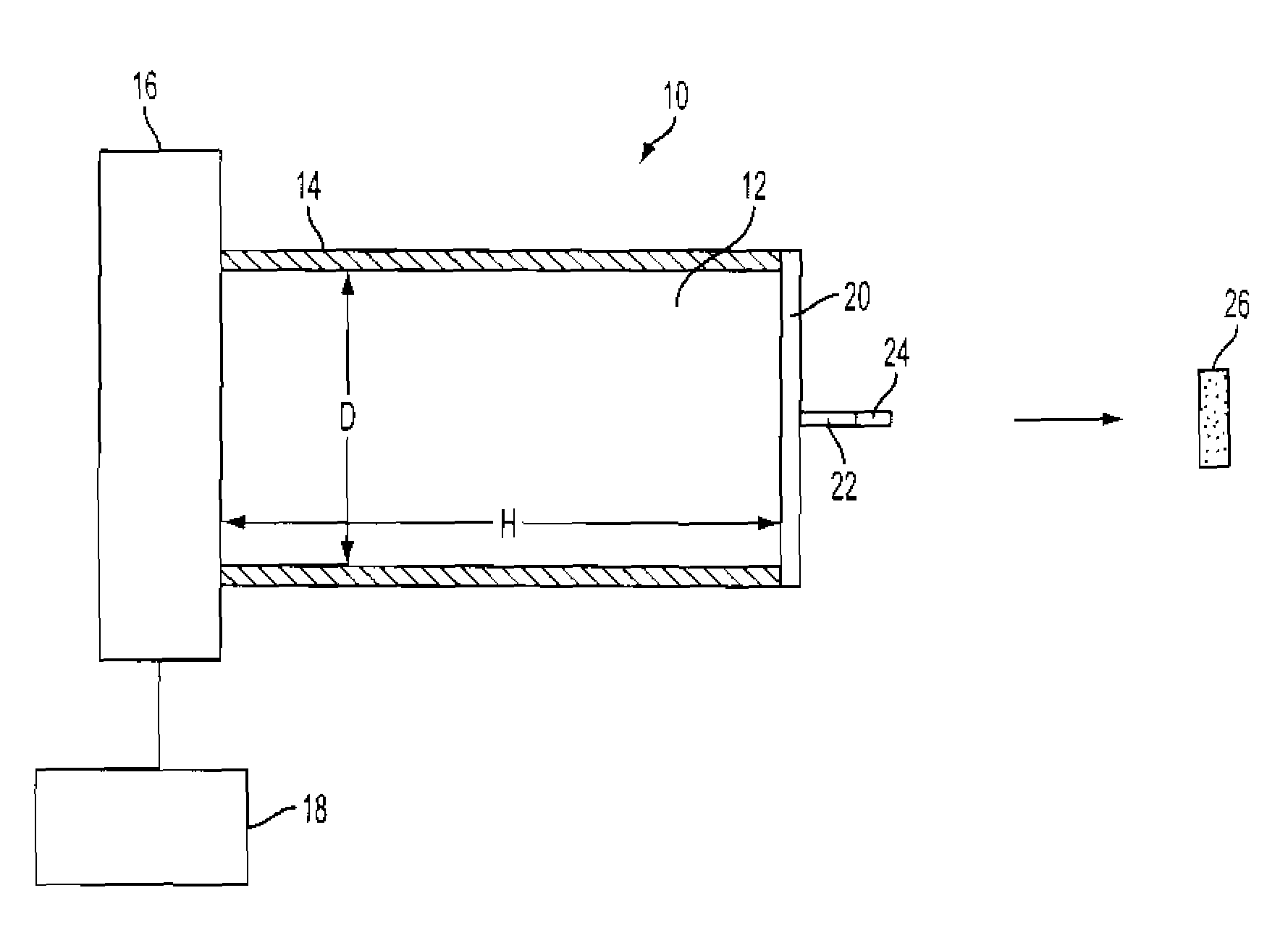
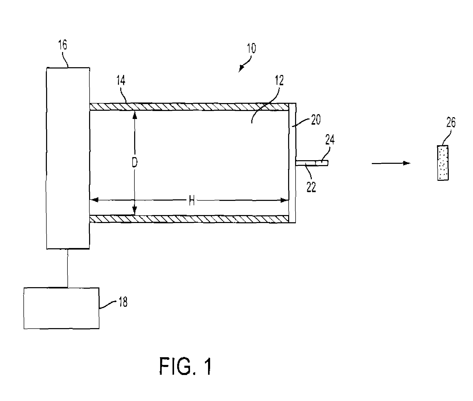
[0019]An exemplary ferroelectric electron and ion generator is shown in FIG. 1 at 10. The generator 10 includes a rod shaped ferroelectric crystal 12 that has a diameter (D) of between 1 micron and 5 centimeters. Thicknesses on the order of 1 mm or less are preferred for small applications where rapid thermal cycling is desired. One mm is the typical size of an object that can be safely inserted into a body for a medical procedure. Also 1 mm is large enough to generate fields of 10.KeV and more. Diameters on the order of 20 to 100 microns are also well suited for many applications use in arrays. Total sizes are much larger for devices and systems where more energy is required. For example, crystal diameters on the order of 3 cm may be used in fusion applications.

[0020]The crystal 12 has a height (H) that is between 1 micron and 5 centimeters. Heights on the order of 1 mm or less are also preferred for small applications with heights of around 100 microns being particularly preferred...


PUM

PropertyMeasurementUnit
diameteraaaaaaaaaa
diameteraaaaaaaaaa
sizeaaaaaaaaaa

Abstract

Ferroelectric, pyroelectric and piezoelectric crystals are used to generate spatially localized high energy (up to and exceeding 100 keV) electron and ion beams, which may be used in a wide variety of applications including pulsed neutron generation, therapeutic X-ray / electron devices, elemental analysis, local scanning chemical analysis, high energy scanning microscopy, point source compact transmission electron microscopy, compact ion beam sources, positron sources, micro-thrusters for ion engines, and improved fusion efficiency especially of the Farnsworth type. The high-energy emission can be created by simply heating the material or by application of external coercive electromagnetic and acoustic fields.

Description

CROSS-REFERENCE TO RELATED APPLICATION[0001]This application claims priority to International Application No. PCT / US2005 / 014003, filed Apr. 22, 2005 and U.S. Provisional Application No. 60 / 572,881, filed May 19, 2005 the entire contents of which are incorporated herein by reference.[0002]This invention was made with government support under the Office of Naval Research, Grant No. N00014-03-1-0762. The U.S. Government has certain fights in this invention.BACKGROUND OF THE INVENTION[0003]1. Field of the Invention[0004]The present invention relates generally to the use of ferroelectric, pyroelectric and piezoelectric crystals for energy transduction via high-energy emissions (HEE). The HEE can be created by simply heating the material or by application of external coercive electromagnetic and acoustic fields. The present invention is directed to the use of such crystals to generate spatially localized high energy (up to and exceeding 100 keV) electron and ion beams, which may be used i...

Claims


Application Information

Patent Timeline
Patent Type & Authority Patents(United States)
IPC IPC(8): H01J27/00
CPCB82Y10/00H01J27/02H01J1/30H01J2201/306
Inventor PUTTERMAN, SETHGIMZEWSKI, JAMES K.NARANJO, BRIAN B.
Owner RGT UNIV OF CALIFORNIA
Why Eureka
Try Eureka