Automobile scanning system

a scanning system and automobile technology, applied in the direction of material analysis, material analysis using wave/particle radiation, instruments, etc., can solve the problems of inability to visually detect persons and contraband hidden in the dashboard or within the seats, time-consuming and often ineffective visual inspection of automobiles, and prior art systems cannot readily distinguish organic matter, etc., to achieve uniform radiation exposure and facilitate the inspection of automobiles

Active Publication Date: 2010-06-22
LEIDOS
View PDF54 Cites 97 Cited by
  • Summary
  • Abstract
  • Description
  • Claims
  • Application Information

AI Technical Summary

Benefits of technology

[0006]It is therefore the goal of the invention to provide an improved method and apparatus for detecting security threats and contraband concealed within automobiles passing through a security check point. Another goal of the invention is to facilitate the inspection of automobiles for the presence of explosives, hidden persons and contraband. Yet another goal is to provide a dual-energy imaging apparatus and method capable of detecting organic objects in the presence of overlying steel. A further goal is to provide a uniform radiation exposure to automobiles being examined regardless of the automobile's speed.

Problems solved by technology

Searching the automobile by visual inspection is time consuming and often ineffective.
For instance, persons and contraband hidden in the dashboard or within the seats cannot be visually detected.
However, prior art systems cannot readily distinguish the organic matter that comprises security threats from the steel forming the automobile.
Further, this inability prevents the prior art systems from employing automated threat detection software programs.
Still further, prior art systems are inefficient in producing contraband-revealing images at the ultra-low radiation doses that are acceptable for such security examination.

Method used


Image

  • Automobile scanning system
  • Automobile scanning system
  • Automobile scanning system

Examples


Embodiment Construction

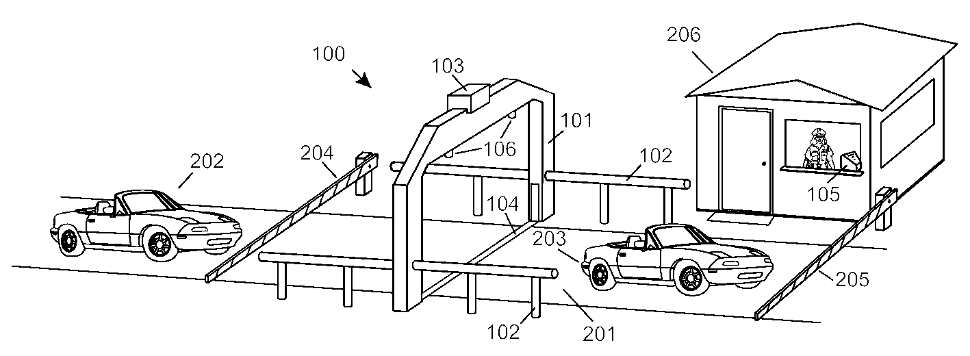
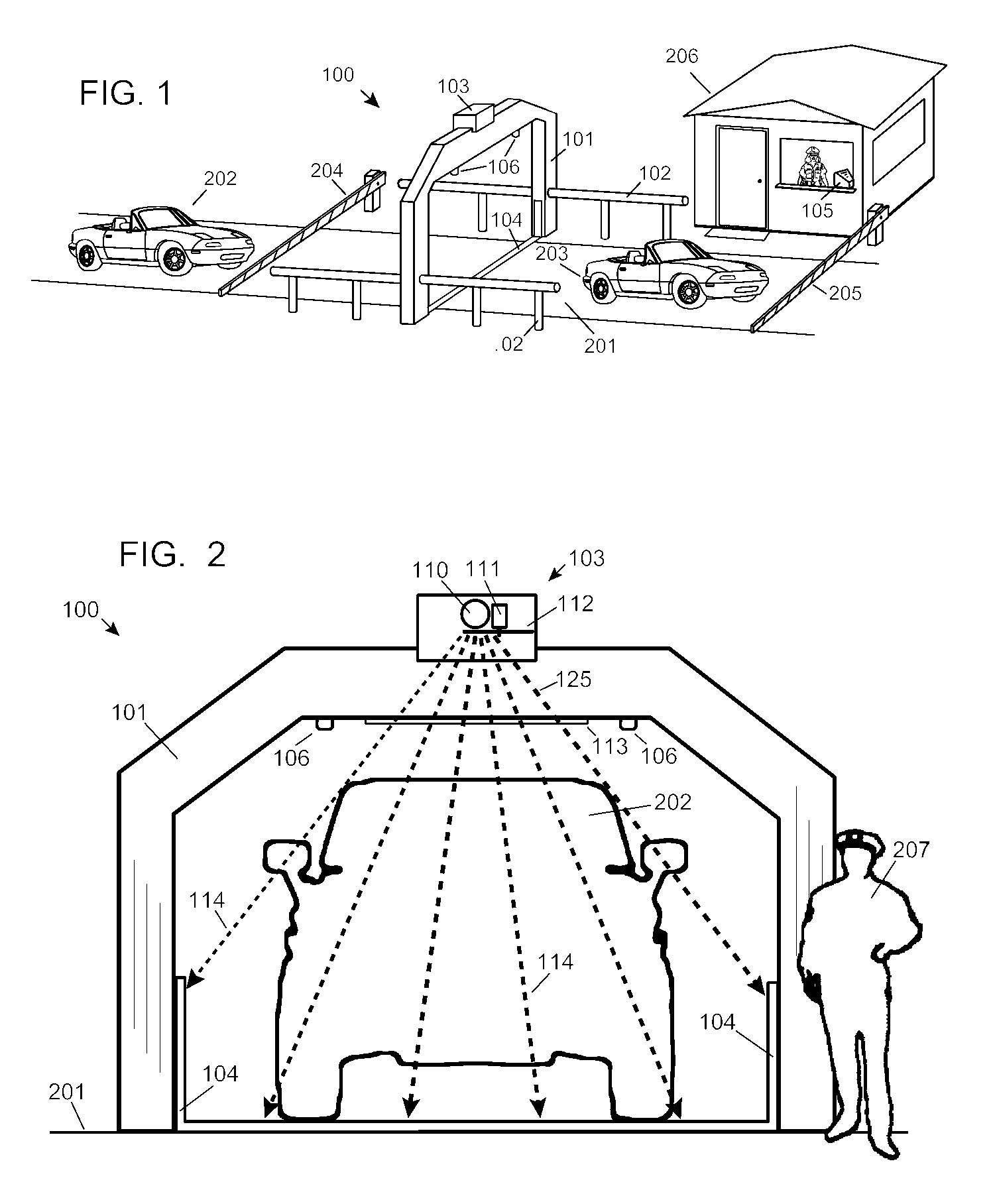
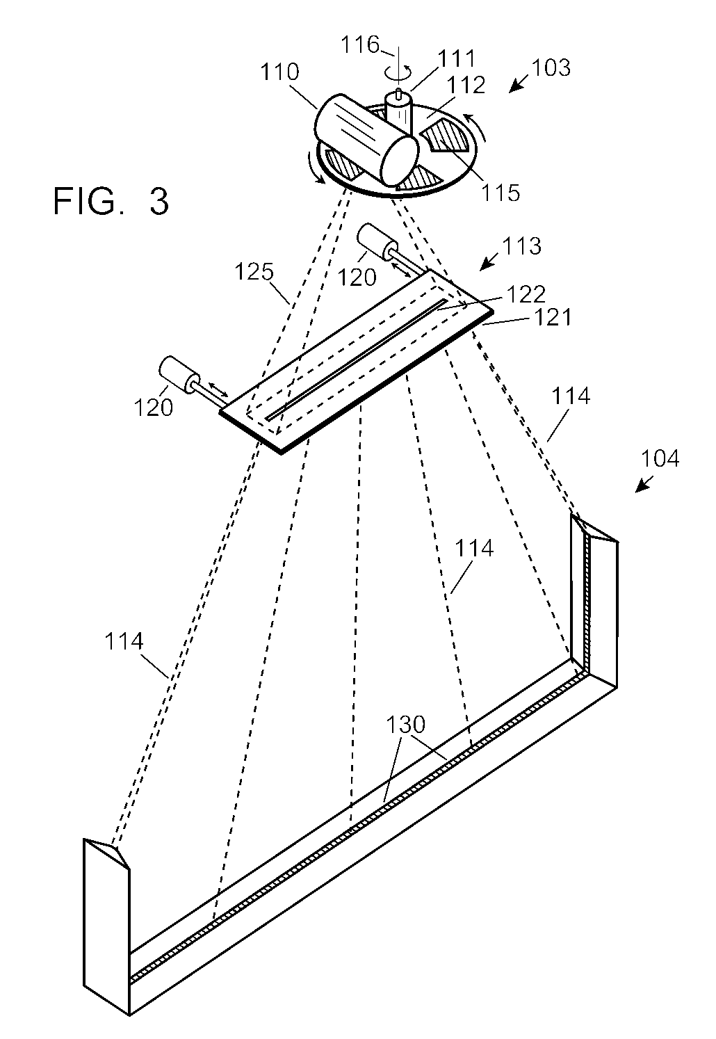
[0016]FIG. 1 shows the overall general operation of the Invention. The scanning apparatus 100 is contained within an archway 101, about 3.0 m high and 3.0 m wide, spanning across the roadway 201. The automobile being examined 202 approaches the scanning apparatus and is stopped by a first gate-arm 204. The first gate-arm 204 is raised, allowing the automobile 202 to slowly drive through the archway 101 until stopped by the second gate-arm 205, at a position 203 after the archway 101. An x-ray assembly 103 is mounted at the top of the archway 101, directing a fan beam of x-rays downward to a linear array detector assembly 104, resting on the roadway 201.

[0017]Automobile motion sensors 106 provide an electronic output of the speed of the automobile 202, 203 as it passes through the archway 101. Support members 102 hold the archway 101 upright and prevent persons on foot from entering the x-ray examination area. The x-ray image data generated by the scanning apparatus 100 is received b...


PUM

PropertyMeasurementUnit
thickaaaaaaaaaa
thickaaaaaaaaaa
widthaaaaaaaaaa

Abstract

A dual-energy x-ray imaging system searches a moving automobile for concealed objects. Dual energy operation is achieved by operating an x-ray source at a constant potential of 100 KV to 150 KV, and alternately switching between two beam filters. The first filter is an atomic element having a high k-edge energy, such as platinum, gold, mercury, thallium, lead, bismuth, and thorium, thereby providing a low-energy spectrum. The second filter provides a high-energy spectrum through beam hardening. The low and high energy beams passing through the automobile are received by an x-ray detector. These detected signals are processed by a digital computer to create a steel suppressed image through logarithmic subtraction. The intensity of the x-ray beam is adjusted as the reciprocal of the measured automobile speed, thereby achieving a consistent radiation level regardless of the automobile motion. Accordingly, this invention provides images of organic objects concealed within moving automobiles without the detritus effects of overlying steel and automobile movement.

Description

[0001]This patent application claims benefit under 35 U.S.C., 119(e) of the U.S. provisional application 60,943,040 filed on Jun. 9, 2007.BACKGROUND OF THE INVENTION[0002]This invention relates to the x-ray imaging of automobiles to detect explosives, hidden persons, contraband, and other security threats.[0003]Criminals and terrorists frequently conceal security threats in automobiles, such as explosives being transported into underground parking facilities for the purpose of destroying skyscrapers; illicit drugs being smuggled across borders; and illegal immigrants being brought into the country. Searching the automobile by visual inspection is time consuming and often ineffective. For instance, persons and contraband hidden in the dashboard or within the seats cannot be visually detected. X-ray inspection systems are now in use that can detect these security threats to some extent. These prior art systems use x-rays that are either transmitted through the automobile, or back scat...

Claims


Application Information

Patent Timeline
Patent Type & Authority Patents(United States)
IPC IPC(8): G01N23/087
CPCG01N23/087G01V5/0066G01V5/0041G01N2223/424
Inventor SMITH, STEVEN WINN
Owner LEIDOS
Why Eureka
Try Eureka