Fuel efficient hydraulic power steering

a technology of hydraulic power steering and fuel-efficient, which is applied in the direction of fluid couplings, positive displacement liquid engines, couplings, etc., can solve problems such as undesirable or impractical systems

Inactive Publication Date: 2010-06-29
FORD GLOBAL TECH LLC
View PDF13 Cites 6 Cited by
  • Summary
  • Abstract
  • Description
  • Claims
  • Application Information

AI Technical Summary

Benefits of technology

[0008]The inventor established the following design scheme in developing the invention with the objective of maximizing energy efficiency of hydraulic power steering systems—particularly those with higher steering load requirements.
[0010]Turn off the pump when there is no steering load—As stated earlier, prior studies have shown that fuel consumption in the unloaded mode can dominate the fuel consumed under load. Therefore, this is a key to minimizing fuel consumption.
[0011]Use a closed center steering gear valve to eliminate fluid flow through the system when there is no steering load. Conventional open center valves require constant flow at all times. A closed center valve allows fluid to be stored upstream in the system and delivered to the gear on demand.
[0012]Add an accumulator to manage steering load / unload transitions. This enables initial steering assist (and / or brake assist if equipped with hydra boost) while the pump is being engaged at the onset of a steering (and / or braking) event. Prior studies with clutched pumps without accumulators have shown unacceptable response. The closed center steering gear valve provides flow on demand and in proportion to steering wheel rate rather than continuous flow, which minimizes accumulator size.
[0014]Use proportional hydraulic valve controls to control assist and pump flow. Proportional control allows supply and demand to balance hydraulically without the need for complicated and costly electronic control strategies.

Problems solved by technology

However, the size and cost of electric motors needed for higher steering load applications make these systems undesirable or impractical at this point in time.

Method used


Image

  • Fuel efficient hydraulic power steering
  • Fuel efficient hydraulic power steering
  • Fuel efficient hydraulic power steering

Examples


Embodiment Construction

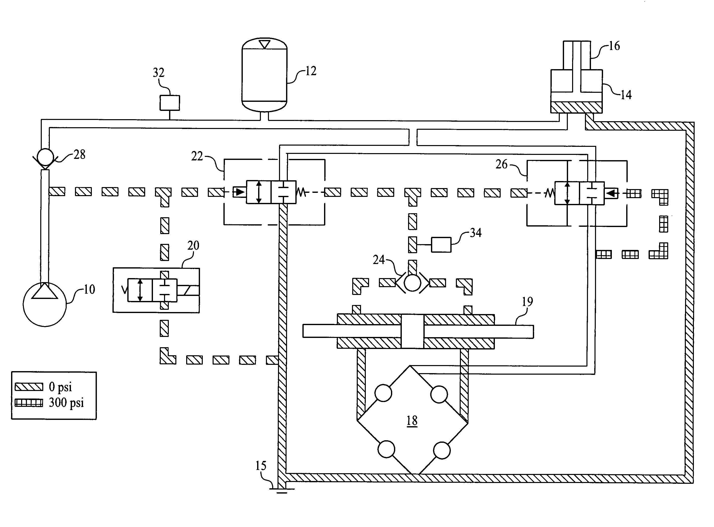
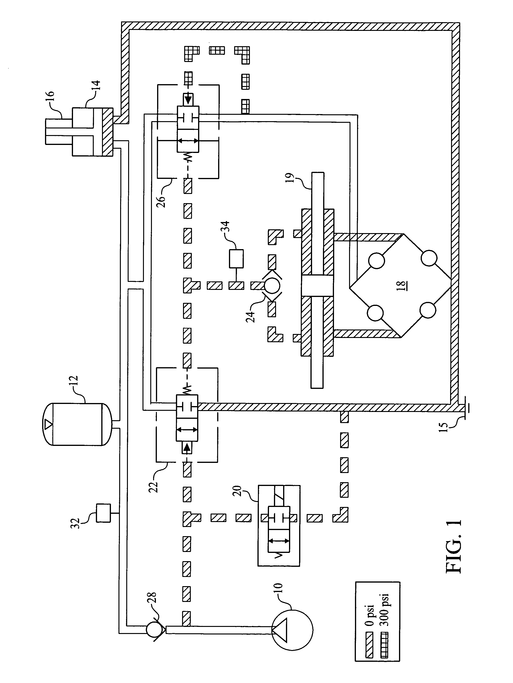
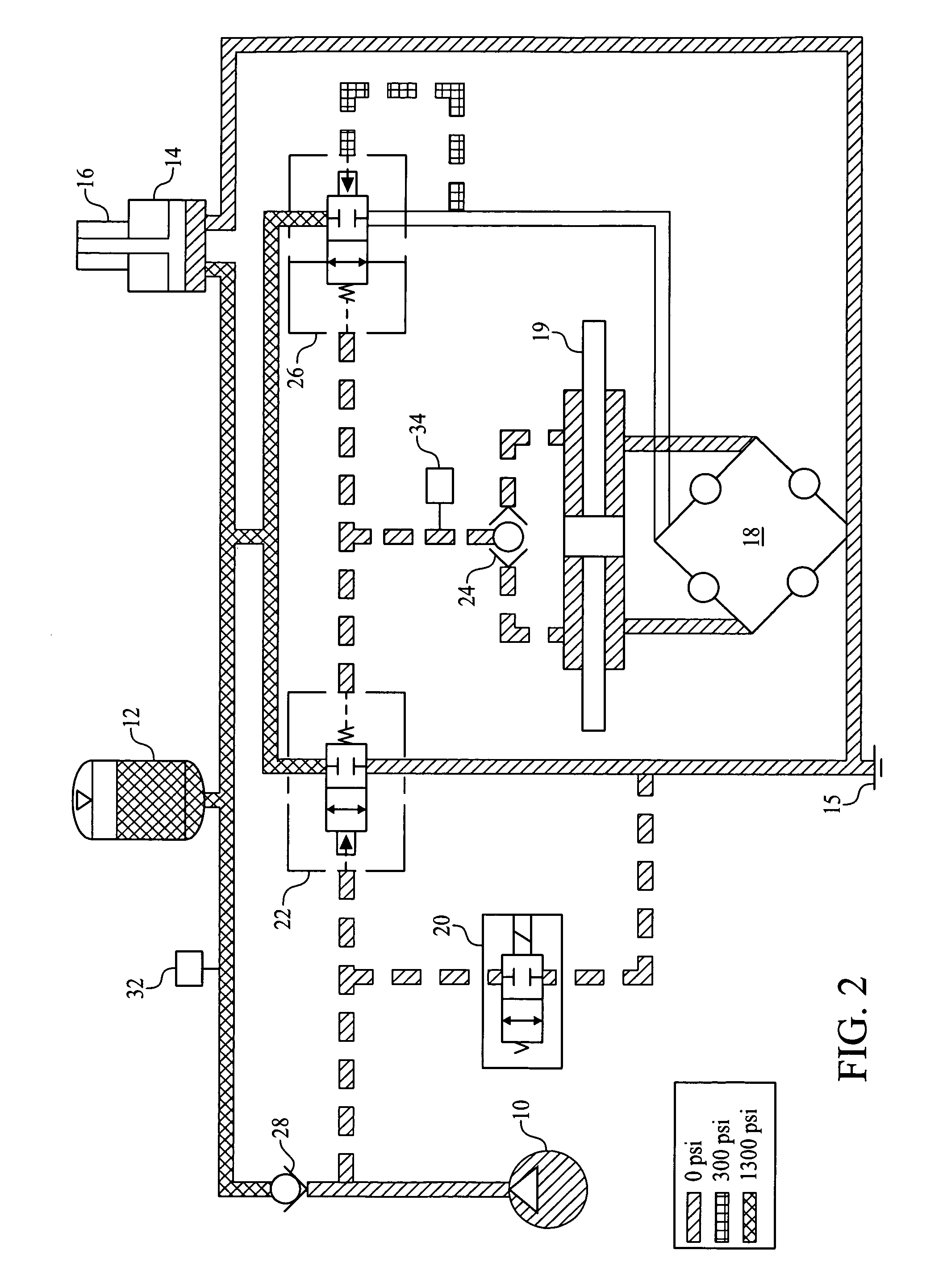
[0033]FIGS. 1-10 share the following components in the hydraulic power steering system: a pump / clutch assembly 10, an accumulator 12, a brake hydra boost 14 with brake master cylinder 16, a steering gear 19, a solenoid valve 20 that is normally open, a relief valve 22 that is normally closed, a closed centered, (gear valve or) steering valve 18, a shuttle valve 24, a control valve 26 that is normally open, a check valve 28 downstream of the pump / clutch assembly 10, a pressure switch 32 in the accumulator circuit, a pressure switch 34 in the reference pressure circuit downstream of shuttle valve 24 and reservoir 15.

[0034]The clutch of the pump / clutch assembly 10 engages the pump when there is a steering demand or accumulator needs to be charged. Shuttle valve 24 monitors pressure on each side of the piston in steering gear 19 and provides the higher of the two pressures to the reference pressure circuit. Accumulator 12 is used to store power steering fluid under pressure. Flow from a...


PUM


Abstract

A hydraulic power steering system that maintains proportional pressure control between an input side of a gear and assist pressures internal to the steering gear by relying upon a control valve. A pressure differential is maintained between the input side of a gear and assist pressures internal to the steering gear throughout certain events. Those events include running the pump to fully charge the accumulator, idling the pump after fully charging the accumulator, discharging pressure from the fully charged accumulator at an onset of a steering event having a demand for steering load, recovering the discharged pressure of the accumulator by running the pump after turning on the pump at the onset of the steering event, and opening the relief valve in the valve manifold during the steering event.

Description

BACKGROUND OF THE INVENTION[0001]1. Field of the Invention[0002]The invention relates to a hydraulic power steering system that continuously provides a source for hydraulic assist to a steering gear while allowing the pump to be idled when there is no steering demand to reduce energy consumption.[0003]2. Description of Related Art[0004]Conventional hydraulic power assist steering systems employ an open center valve at the steering gear and a pump, which supplies constant flow through an open loop hydraulic circuit. Fluid is pumped through the system at all times while the engine is running regardless of steering load. By closing ports within the steering valve creating pressure internal to the gear and in the hydraulic circuit upstream to the pump, boost or steering assist is created. Running a hydraulic pump continuously in this type of system ensures good response to a steering input but is inefficient when there is no steering load. Restrictions in the hydraulic system can create...

Claims


Application Information

Patent Timeline
Patent Type & Authority Patents(United States)
IPC IPC(8): B62D5/065F04B49/00
CPCB62D5/065B62D5/063
Inventor MILLER, TODD ROBERT
Owner FORD GLOBAL TECH LLC
Why Eureka
Try Eureka