
High definition multi-media interface

a multi-media interface, high-definition technology, applied in the field of multi-channel interfaces, can solve the problems of significant degradation of the signal-to-noise ratio (snr) of the receiver, severe limits to the performance of the receiver,

Active Publication Date: 2010-06-29
ENTROPIC COMM INC
View PDF28 Cites 32 Cited by
  • Summary
  • Abstract
  • Description
  • Claims
  • Application Information

AI Technical Summary

Benefits of technology

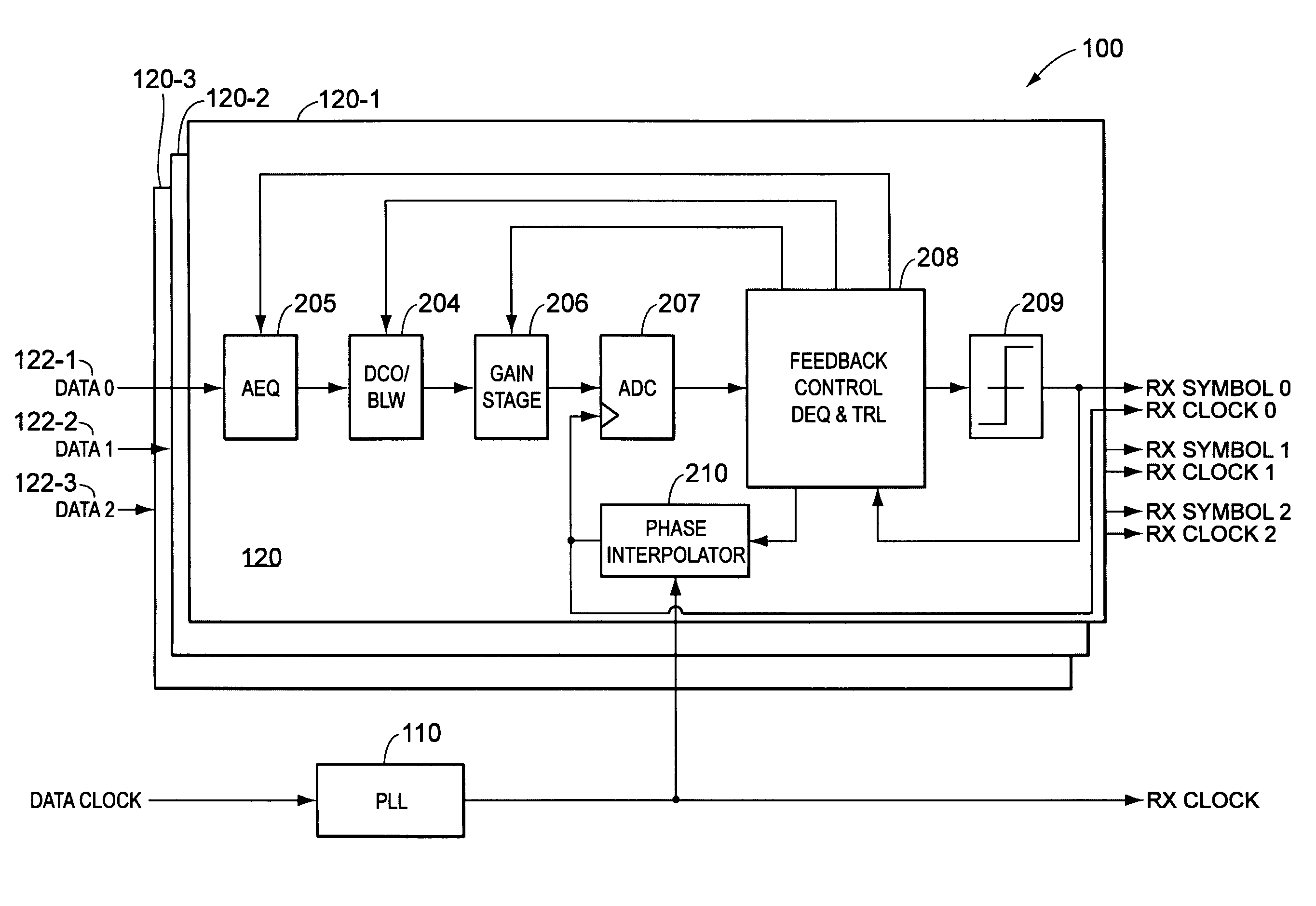
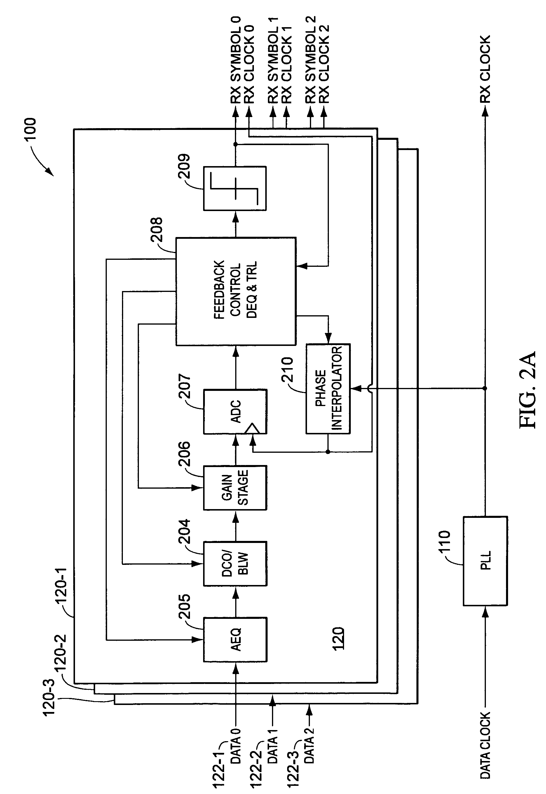
"The present invention provides a multi-channel receiver system with a digital control block that can digitally control the analog portion of the receiver. The receiver system includes an analog portion with an analog equalizer and a decision feedback equalizer, as well as a digital control block that includes a digital equalizer, a decision feedback equalizer, a gain stage, and a phase block. The receiver system can also include a clock signal channel and a plurality of data channels. The invention allows for improved signal quality and equalization of the data channels, as well as improved timing recovery."

Problems solved by technology

This approach severely limits the performances of these receivers because of the inability to adapt to the operating environment of the system.
This inability can become apparent in harsh environments, such as large attenuation across the cable or large amounts of timing jitter, or if the environment is changing due to, for example, temperature fluctuations or changes in the channel properties.
The lack of equalization options limits the ability of these receivers to provide the optimum amount of channel equalization, leading to significant degradation of the signal-to-noise ratio (SNR) of the receiver.
Minimal timing recovery options limit the amount of jitter that the receiver can track and correct, further leading to a degradation of the performance of the receivers.
Together, these issues lead to an increased bit-error rate (BER), limit the cable length over which the receiver can successfully operate, and limit the ability of the receiver to cope with poor connectors and low quality board materials.

Method used


Image

  • High definition multi-media interface
  • High definition multi-media interface
  • High definition multi-media interface

Examples


Embodiment Construction

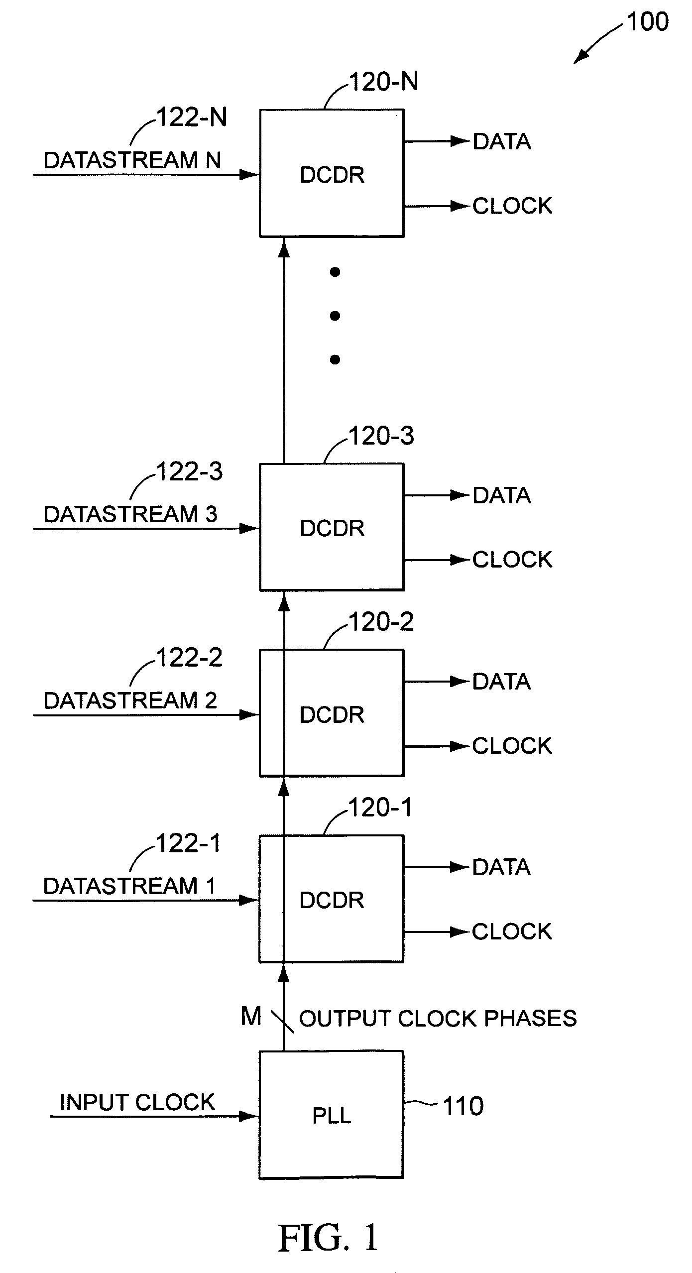
[0031]A receiver system according to some embodiments of the present invention can be utilized for transmissions between integrated circuit chips. In some embodiments, the receiver can receive multiple streams of data. The receiver then recovers the data and the clock signal from each data stream and provides clock and data signals from each data stream to the remainder of the integrated circuit chip or set of chips. Although the example disclosed herein is most applicable to HDMI applications, transceivers according to the present invention can also find applicability to any serial backplane applications, wired communication including HDMI, HDTV, and Fiber Channel, or optical communications systems including Sonet and Ethernet.

[0032]The optimum clock signals corresponding to each of the data streams may vary from one another in both phase and frequency, although in an HDMI system there is only a phase offset. Further, the frequency of the optimum clock signals for receipt of data f...


PUM


Abstract

A receiver for a multi-channel system such as a HDMI system is presented. In accordance with the present invention, the receiver receives one of the plurality of channels and includes an analog portion, a digital-to-analog converter, and a digital control block that provides digital control signals to the analog portion. Equalization can be accomplished partially or wholly in the analog domain and digitally controlled by a digital control loop. A digital equalizer can also be included. A decision feedback equalizer can be implemented that sums an analog output signal into the analog data stream. Timing recovery can be accomplished by digital control of a phase interpolator or delay locked loop that receives a plurality of phases from a timing circuit coupled to receive a clock signal.

Description

BACKGROUND[0001]1. Field of the Invention[0002]The present invention is related to multi-media receivers and, in particular, to a multi-channel interface such as a high-definition multi-media interface.[0003]2. Discussion of Related Art[0004]High-definition multimedia is becoming increasingly common-place. Continuously, consumers are demanding greater levels of quality in multimedia entertainment. High-Definition Multimedia Interface (HDMI) refers to a technology that is being developed to allow the seamless transfer of uncompressed digital audio and video data between devices. HDMI is the first industry-supported, uncompressed, all-digital audio and video interface. HDMI is utilized to interface between devices such as digital set-top boxes, DVD players, and televisions, or any other device that transmit or receive digital audio and video data.[0005]The HDMI standard supports standard, enhanced, and high-definition video, plus multi-channel digital audio on a single cable. Further,...

Claims


Application Information

Patent Timeline
Patent Type & Authority Patents(United States)
IPC IPC(8): H04B1/10H04N21/426H04N21/436
CPCH04L25/03878H04L25/03057H04L7/0062H04L7/0334H04N5/44
Inventor BRYAN, THOMASWEBB, STEWARTSALLAWAY, PETERMANICKAM, TULSIRAGHAVAN, SREEN
Owner ENTROPIC COMM INC
Learn More