Turbofan engine

a technology of turbofan and engine body, which is applied in the direction of liquid fuel engine components, non-positive displacement fluid engines, combustion air/fuel air treatment, etc., can solve the problems of increasing the weight of the engine, achieve high engine efficiency, reduce the flow, and reduce the pressure loss

Active Publication Date: 2010-07-06
IHI CORP
View PDF24 Cites 13 Cited by
  • Summary
  • Abstract
  • Description
  • Claims
  • Application Information

AI Technical Summary

Benefits of technology

[0012]The present invention is made by solving the problem mentioned above. In other words, an object of the present invention is to provide a turbofan engine which can increase an intake air flow rate of a fan first-stage moving blade without enlarging a diameter of a fan and an inner diameter of a casing, whereby it is possible to increase a bypass ratio, achieve a favorable mileage and a low noise, and reduce a weight of an engine.

Problems solved by technology

However, in the turbofan engine mentioned above, there is a problem that a fan first-stage moving blade (an up-front fan) and an inner diameter of a casing surrounding the fan first-stage moving blade are enlarged by enlarging the bypass ratio, and a weight of the engine is increased.

Method used


Image

  • Turbofan engine
  • Turbofan engine
  • Turbofan engine

Examples


first embodiment

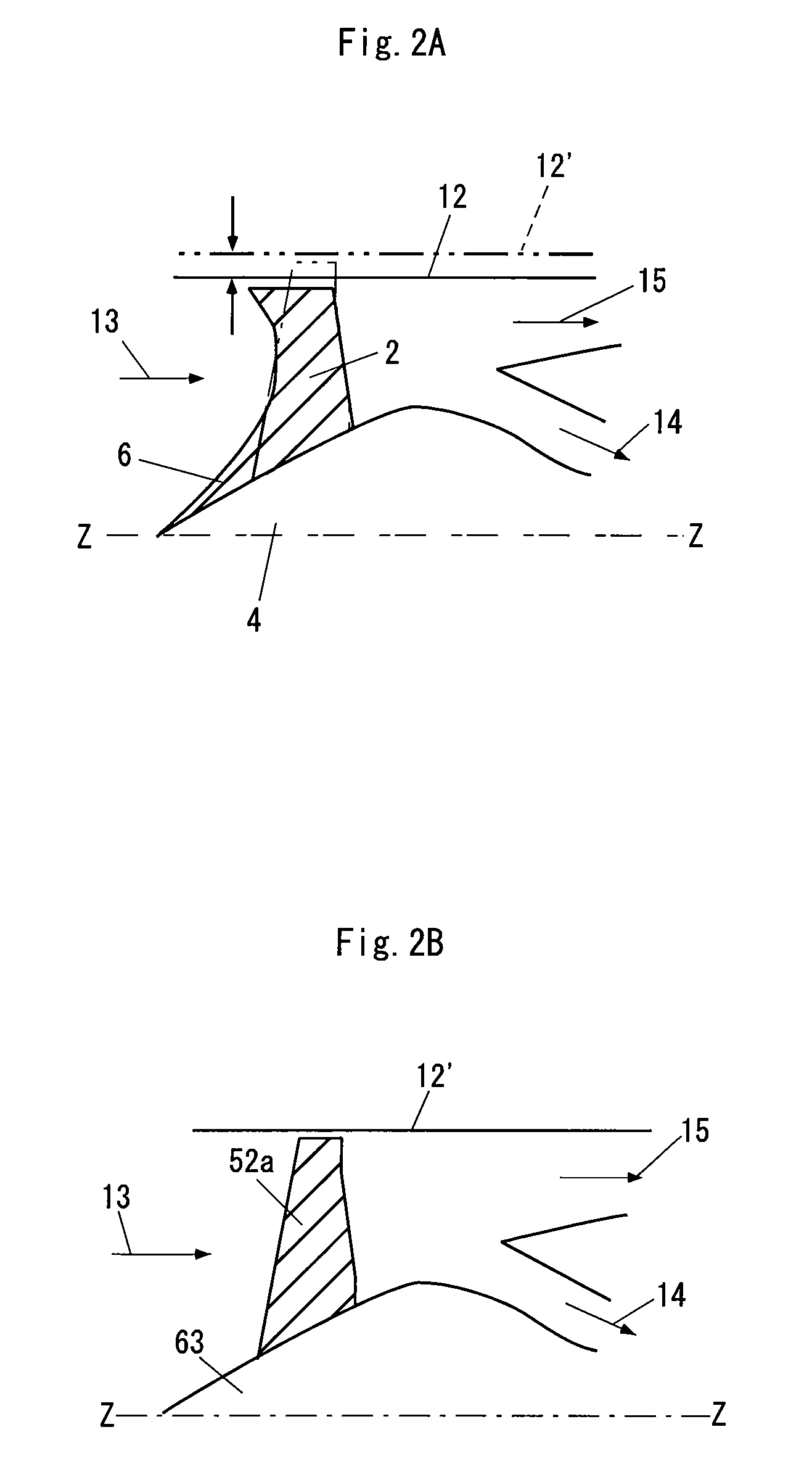
[0062]FIG. 2A is a partially structural drawing of a turbofan engine in accordance with the present invention. Further, FIG. 2B shows a conventional embodiment. In each of the drawings, reference symbol Z-Z denotes a center line of an engine, reference numerals 12 and 12′ denote an inner diameter of a casing, reference numeral 13 denotes a flow of an inflow air, reference numeral 14 denotes a core flow and reference numeral 15 denotes a bypass flow.

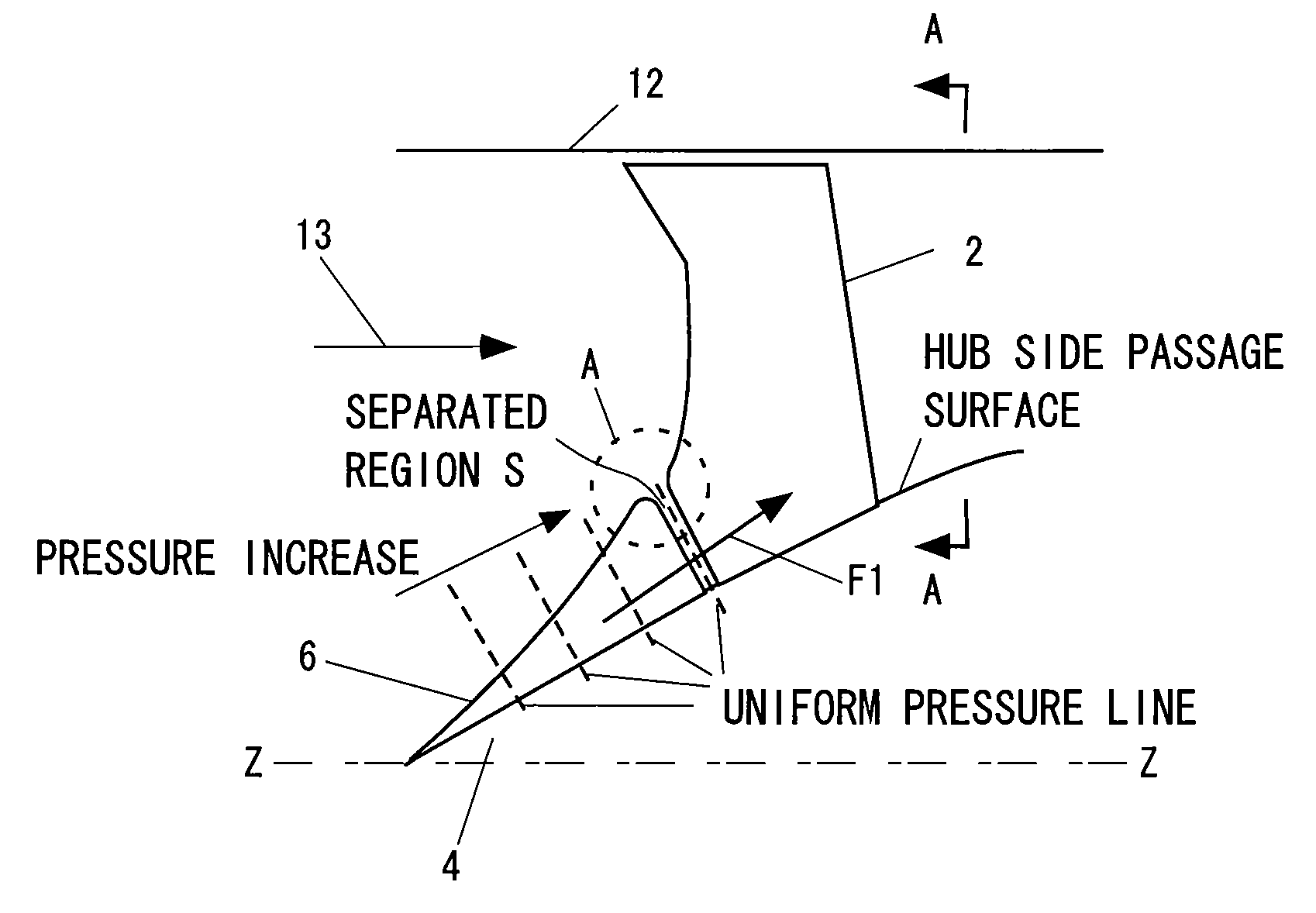
[0063]As shown in FIG. 2A, the turbofan engine in accordance with the present invention is provided with a fan first-stage moving blade 2 for taking an air therein, and a spinner 4 rotationally driving the fan first-stage moving blade 2. Further, the spinner 4 has a spiral blade 6 in a front face thereof. The spiral blade 6 extends spirally to an outer side in a radial direction from an axis Z of the spinner 4, sucks the air from the front face of the spinner, and compresses the air so as to supply to the fan first-stage moving blade 2.

[0...

second embodiment

[0072]FIG. 4 is a partially structural drawing of a turbofan engine in accordance with the present invention. As shown in this drawing, in accordance with the present embodiment, the spiral blade 6 is separated from the fan first-stage moving blade 2, and the same number of spiral blades as the fan first-stage moving blades 2 are arranged in an upstream side of the fan first-stage moving blade 2.

[0073]A strain is generated in a radial direction of the spiral blade 6 and the fan first-stage moving blade 2 due to a centrifugal force of a rotational motion, however, the strains are different between the both due to the difference of the both. Accordingly, in the case that the spiral blade 6 and the fan first-stage moving blade 2 are coupled such as the first embodiment 1, there can be considered that a harmful stress is generated due to the difference of the strains. Further, there can be considered that it is hard to couple the spiral blade 6 and the fan first-stage moving blade 2 due...

third embodiment

[0089]In the normal blade row, a boundary layer tends to be developed in a back side, and the pressure loss is generated in the portion. However, in the present invention, it is possible to expect an effect of blowing away the boundary layer in the back side of the fan first-stage moving blade 2 by arranging the spiral blade 6 in such a manner as to shift the phase to the back side of the fan first-stage moving blade 2 in the peripheral direction, whereby it is possible to reduce the pressure loss and it is possible to improve the engine performance. In this case, if the phase of the spiral blade 6 is shifted to the body side of the fan first-stage moving blade 2, the flow is disarranged, so that an adverse effect is generated.

[0090]Further, since the deformations in the peripheral direction and the axial direction are structurally generated in the fan first-stage moving blade 2 at a time of rotating, it is necessary to form the fan in such a manner as to prevent the spiral blade 6 ...


PUM


Abstract

A turbofan engine of the invention is provided with a fan first-stage moving blade for taking an air therein, and a spinner rotationally driving the fan first-stage moving blade, the spinner has a spiral blade extending spirally to an outer side in a radial direction, sucking the air from a front face of the spinner and supplying the air to the fan first-stage moving blade. Further, the fan first-stage moving blade and the spinner are integrally coupled, and the spiral blade and the fan first-stage moving blade are formed such that blade surfaces are smoothly connected.

Description

BACKGROUND OF THE INVENTION[0001]1. Technical Field of the Invention[0002]The present invention relates to a turbofan engine which has a high bypass ratio and can achieve a favorable mileage and a low noise.[0003]2. Description of Related Art[0004]FIG. 1 is a schematic block diagram of an aircraft engine 51 (a turbojet engine). As shown in this drawing, the turbojet engine is provided with a fan 52 taking an air therein, a compressor 53 compressing the intake air, a combustor 54 burning a fuel by the compressed air, a turbine 55 driving the fan 52 and the compressor 53 by a combustion gas of the combustor 54, an after burner 56 afterburning for increasing a thrust and the like.[0005]The after burner 56 comprises a flame holder 57 having a triangular cross section or the like and forming a circulating region in a downstream side so as to hold the flame, a fuel nozzle 58 for jetting the fuel, a spark plug 59 and the like, and is structured such as to jet from an exhaust nozzle 62 thro...

Claims


Application Information

Patent Timeline
Patent Type & Authority Patents(United States)
IPC IPC(8): F04D17/06
CPCF01D5/021F01D5/141F02C7/04F04D29/324F04D29/384F02K3/06Y02T50/673Y02T50/671F05D2250/70Y02T50/60
Inventor KODAMA, HIDEKAZUGOTO, SHINYAMIZUTA, IKUHISAMIYAMOTO, YOSHIYUKIMUROOKA, TAKESHI
Owner IHI CORP
Why Eureka
Try Eureka