Vascular coupling device

a coupling device and vascular technology, applied in the field of fluid withdrawal or delivery, can solve the problems of affecting the effect of fluid withdrawal,

Inactive Publication Date: 2010-07-06
ACTIVEIN
View PDF26 Cites 6 Cited by
  • Summary
  • Abstract
  • Description
  • Claims
  • Application Information

AI Technical Summary

Benefits of technology

[0016]c) aiding in the break-up and / or evacuation of blocking material such as a clot that forms outside the catheter;
[0017]d) opening one or more coverings that prevent clots from forming inside the catheter;
[0036]wherein said hollow tube has a portion sized and shaped to prevent the insertion of more than 10 cm of said hollow tube in the body of a patient when implanted so that said hollow tube is adapted to be implanted in the surface vein and withstand the unimpeded intake of fluid for a period of one or more days.

Problems solved by technology

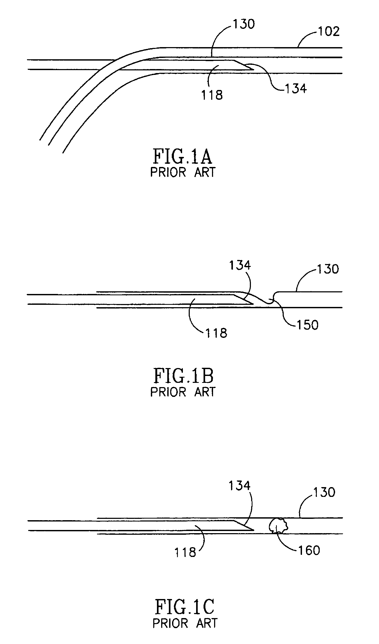
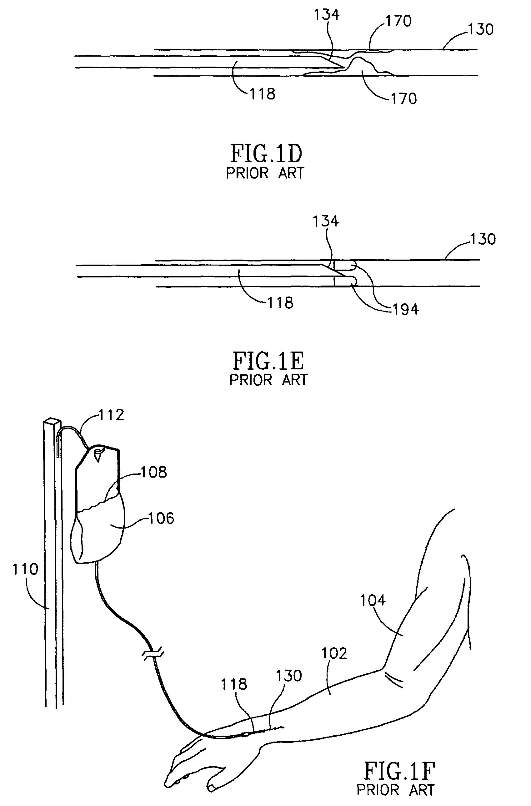
Unfortunately, when catheter 118 is left in one place for a few days or even as briefly as one day, particularly when fluid withdrawal is not on a continuous basis, blockage of catheter front inlet 134 often occurs.
In all of these cases, vein 130 becomes unsuitable, often permanently, for further fluid withdrawal.
The placement of a shunt is a relatively expensive and hazardous procedure in comparison to percutaneous access of vein 130 with catheter 118.

Method used


Image

  • Vascular coupling device
  • Vascular coupling device
  • Vascular coupling device

Examples


Embodiment Construction

[0075]In an exemplary embodiment of the invention, a portion of catheter 118 is provided with one or more extendible extensions, in one or more configurations, that aid in fluid withdrawal from vein 130. FIG. 2A is a cut-away side view of balloon extensions 122 extending away from catheter 118. Balloon extensions 122 extend away from catheter 118 when they are caused to expand by the introduction of an expansion fluid 166, such as sterile water, saline, oxygen or nitrogen, introduced through expansion inlet 124 and via one or more passageways 120 into one or more suitable chambers. Extension of balloon extension 122 away from catheter 118 aids in preventing, or prevents, blockage of catheter 118, for example, by one or more of:

[0076]a) removing and / or displacing tissue or a blockage from a catheter;

[0077]b) transposing a catheter inlet away from tissue or a blockage;

[0078]c) aiding in the break-up and / or evacuation of blocking material such as a clot that forms outside the catheter;...


PUM


Abstract

A venous port for withdrawal of fluid in which one or more extensions are provided which can selectively extend to remove impediments from an aperture of the port.

Description

RELATED APPLICATIONS[0001]The present application is a U .S. national application of PCT Application No. PCT / IL03 / 00254, filed on Mar. 26, 2003. This application also claims the benefit under 35 U.S.C. §119(e) of U.S. Provisional Application No. 60 / 367,263. All the disclosures of the above listed applications axe incorporated herein by reference.FIELD OF THE INVENTION[0002]The present invention relates to fluid withdrawal or delivery from a body cavity.BACKGROUND OF THE INVENTION[0003]Connection of a catheter to a blood vessel, for example a vein, is an important medical procedure that allows withdrawal of fluid, for example blood samples, or delivery of fluid, for example nutrients, for a few days up to a few weeks. In the process of fluid delivery and / or withdrawal, for example, the catheter is periodically pulled out of one vein area and inserted into another vein area, for example, every five days.[0004]FIGS. 1A through 1F illustrate typical prior art catheters and a variety of ...

Claims


Application Information

Patent Timeline
Patent Type & Authority Patents(United States)
IPC IPC(8): A61M5/00A61F2/958A61M27/00
CPCA61M25/1002A61M27/00A61M27/002A61M27/008A61M2025/0019A61M2025/1047A61M2025/1072
Inventor SHALEV, ILAN
Owner ACTIVEIN
Why Eureka
Try Eureka