
Plasma etching method

a technology of etching and plasma, which is applied in the direction of electrical discharge tubes, decorative arts, electrical apparatus, etc., can solve the problems of affecting the effect of etching, so as to facilitate and stabilize the electric-discharge effect, reduce the electric-discharge starting voltage, and prolong the residence time of the gas in the chamber

Inactive Publication Date: 2010-07-06
TOKYO ELECTRON LTD +1
View PDF12 Cites 37 Cited by
  • Summary
  • Abstract
  • Description
  • Claims
  • Application Information

AI Technical Summary

Benefits of technology

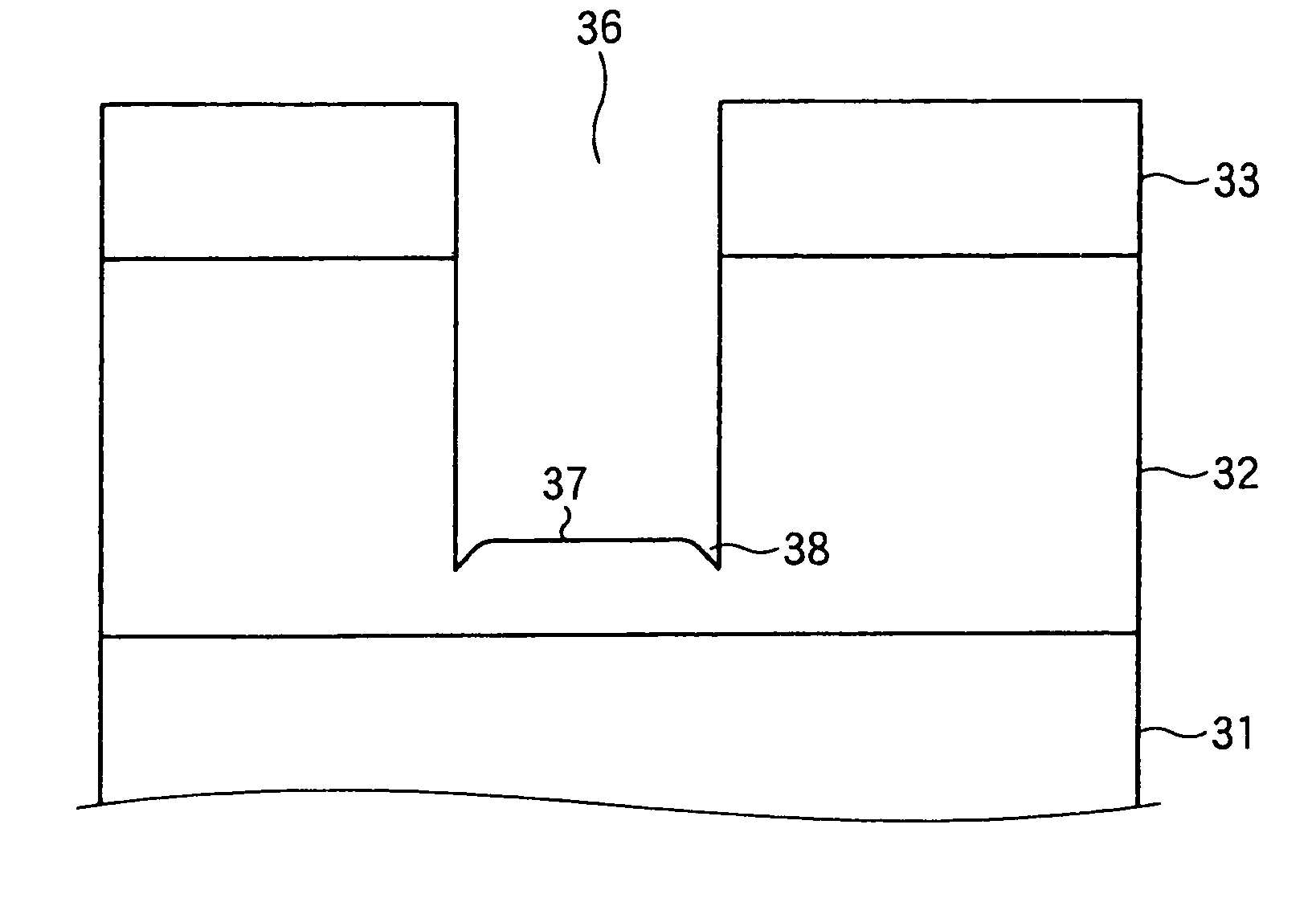
The present invention is a plasma etching method that can prevent the micro-trenching phenomenon when etching organic-material films. This is achieved by controlling the plasma density and ion energy in the etching process. By using a high-frequency electric power with a low bias voltage, the method can achieve a high etching rate while inhibiting micro-trenching. The frequency of the high-frequency electric power applied to the electrodes should be 50 to 150 MHz. The pressure in the chamber should be 1.33 to 13.3 Pa, and the plasma density should be 5×10¹⁰ to 1×1011 cm−3. Overall, this method provides a more effective and efficient way to plasma etch organic-material films.

Problems solved by technology

If the micro-trenching phenomenon is generated, when a filling layer is formed thereafter, the filling layer may be not sufficiently filled into the groove and / or concentration of electric charges may be caused.

Method used


Image

  • Plasma etching method
  • Plasma etching method
  • Plasma etching method

Examples


Embodiment Construction

[0041]An embodiment of the invention will now be described with reference to the attached drawings.

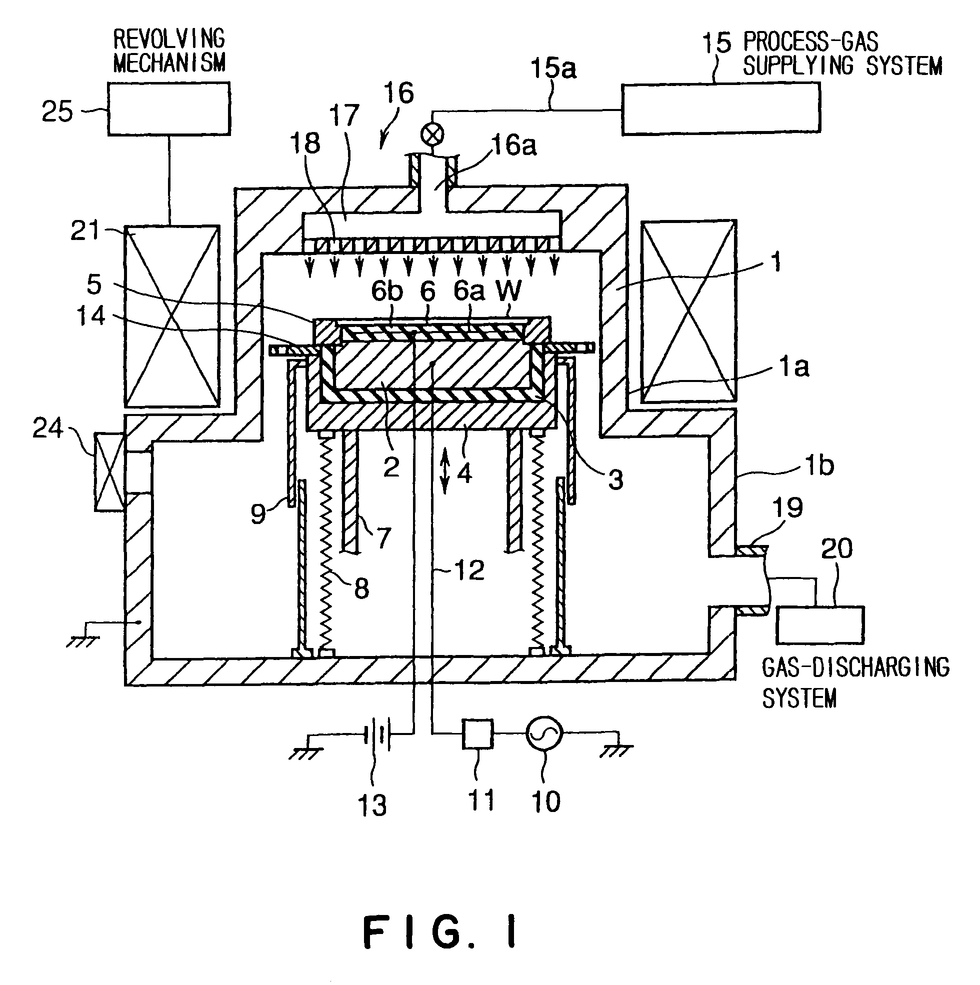
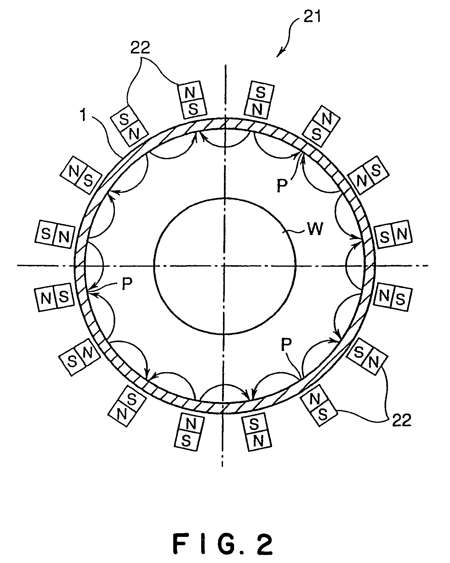
[0042]FIG. 1 is a schematic sectional view showing a plasma etching unit used for carrying out the present invention. The etching unit of the embodiment includes a two-stage cylindrical chamber vessel 1, which has an upper portion 1a having a small diameter and an lower portion 1b having a large diameter. The chamber vessel 1 may be hermetically made of any material, for example aluminum.

[0043]A supporting table 2 is arranged in the chamber vessel 1 for horizontally supporting a wafer W as a substrate to be processed. The supporting table 2 may be made of any material, for example aluminum. The supporting table 2 is placed on a conductive supporting stage 4 via an insulation plate 3. A focus ring 5 is arranged on a peripheral area of the supporting table 2. The focus ring 5 may be made of any conductive material or any insulating material. When the diameter of the wafer W is 200 mmφ, i...


PUM

PropertyMeasurementUnit
widthaaaaaaaaaa
frequencyaaaaaaaaaa
frequencyaaaaaaaaaa

Abstract

The present invention is a plasma etching method including: an arranging step of arranging a pair of electrodes oppositely in a chamber and making one of the electrodes support a substrate to be processed in such a manner that the substrate is arranged between the electrodes, the substrate having an organic-material film; and an etching step of applying a high-frequency electric power to at least one of the electrodes to form a high-frequency electric field between the pair of the electrodes, supplying a process gas into the chamber to form a plasma of the process gas by means of the electric field, and plasma-etching the organic-material film of the substrate by means of the plasma partway in order to form a groove having a flat bottom. A frequency of the high-frequency electric power applied to the at least one of the electrodes is 50 to 150 MHz in the etching step.

Description

FIELD OF THE INVENTION[0001]The present invention relates to a plasma etching method of partway plasma-etching an organic-material film, such as a low-dielectric-constant film (low-k film), formed on a substrate to be processed, such as a semiconductor wafer.DESCRIPTION OF THE RELATED ART[0002]In a wiring step of a semiconductor device, an interlayer dielectric film, which has been formed between wiring layers, may be etched in order to electrically connect the wiring layers. Recently, it has been requested to use a film having a lower dielectric constant as the interlayer dielectric film, in order to achieve more speeding-up of the semiconductor device. Some organic-material films have started to be used as such a film having a lower dielectric constant.[0003]Etching process for the organic-material films is carried out by a plasma etching. Specifically, a pair of opposite electrodes is arranged in a chamber in such a manner that the electrodes are vertically opposite, a semiconduc...

Claims


Application Information

Patent Timeline
Patent Type & Authority Patents(United States)
IPC IPC(8): H01L21/302C23F1/00H01L21/3065H01L21/311
CPCH01J37/32688H01L21/31144H01L21/31138H01J2237/3347
Inventor HONDA, MASANOBUNAGASEKI, KAZUYAHAYASHI, HISATAKA
Owner TOKYO ELECTRON LTD
Learn More