Methods and systems for biometric identification

a biometric identification and biometric technology, applied in the field of biometric identification systems, can solve the problems of large number of servers, large number of systems, and difficulty in iris recognition techniques for some applications, and achieve the effect of improving the acquisition of iris images

Active Publication Date: 2010-07-06
PRINCETON IDENTITY INC
View PDF4 Cites 65 Cited by
  • Summary
  • Abstract
  • Description
  • Claims
  • Application Information

AI Technical Summary

Benefits of technology

[0013]Embodiments of the present invention generally relate to methods for improving performance of an iris recognition system. The methods can include using iris image registration and averaging steps to improve performance. In one embodiment, the iris image is averaged. In another embodiment, the segmented iris image is averaged. In yet another embodiment, the normalized iris image is averaged. In another embodiment, the biometric template is averaged. As used herein, the term ‘averaged’ denotes a combining of two or more entities, such as iris templates, based on a set of rules based on information that can be contained both within and external to the entity, or iris template. The term average, as used herein, is not restricted to the narrower concept of an arithmetic mean. The purpose of the averaging is to create an entity which is better than any one of the individual entities that have been averaged.
[0015]In one embodiment, there is provided an iris recognition method for capturing iris images that provide increased capture volume, decreased acquisition time, increased standoff and the capability of acquisition of iris images from moving subjects.

Problems solved by technology

However, prior iris recognition techniques suffer from several difficulties for some applications.
One difficulty is that when used in systems with large (e.g., 500,000) people in the database, such systems require a large number of servers to accommodate the large number of people in the databases.
Another difficulty is that prior techniques have been designed and optimized for applications in which the false match rate is of paramount importance-neglecting applications in which other factors are more important than the false match rate or in which other engineering tradeoffs should be considered.
Acquisition of high quality iris images is difficult because the human iris is a small target (−1 cm diameter), with relatively low albedo (˜0.15), in the near IR.
Hence, acquisition of iris images of sufficient quality for iris recognition is challenging, particularly from a distance.
A related issue is the standoff distance, the distance between the subject and the iris image acquisition system.
For large databases that are subject to high interrogation rates this consumes many CPU cycles and requires deployment of large collections of computers to provide acceptable response rates.

Method used


Image

  • Methods and systems for biometric identification
  • Methods and systems for biometric identification
  • Methods and systems for biometric identification

Examples


Embodiment Construction

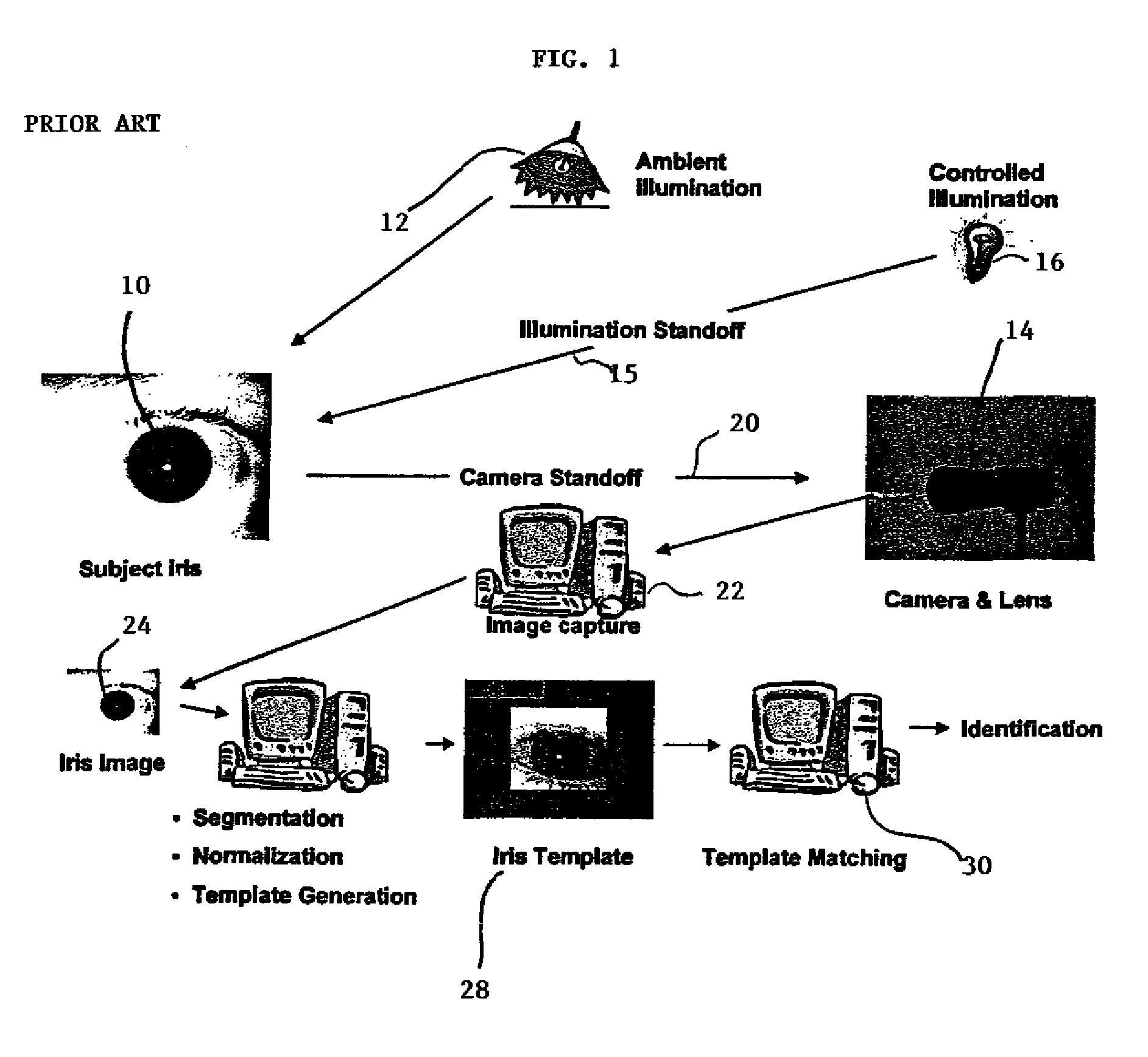
[0026]As described above with reference to FIG. 1, a captured iris image is then segmented, normalized and an iris template (commonly called an iris code) is generated. The template is then matched against an existing database of previously enrolled irises; a match against the database indicates the current iris is the same iris used to create the template that is in the database.

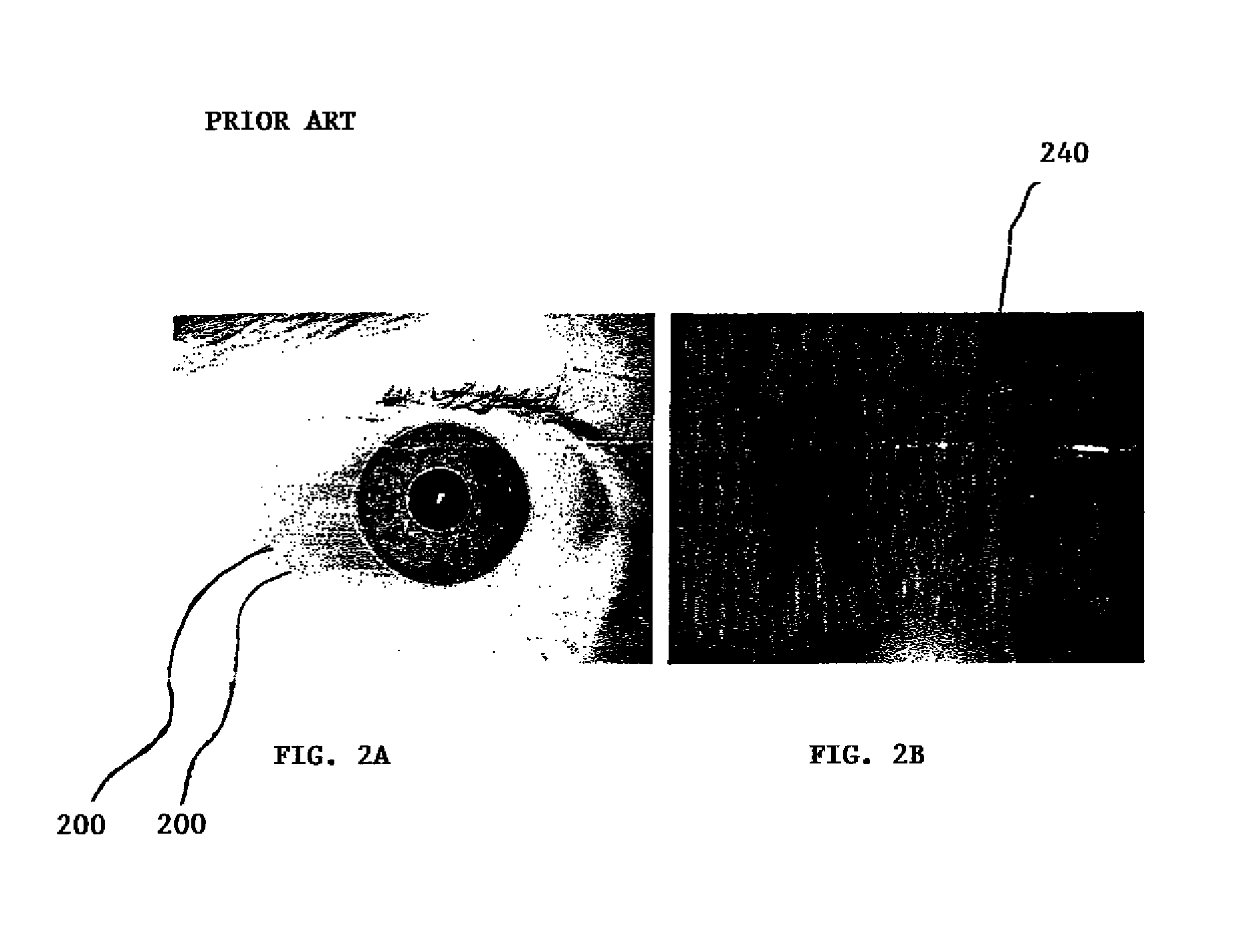
[0027]Segmentation identifies the boundaries of the pupil and iris. Normalization remaps the iris region between the pupil and the sclera (the white of the eye) using a transform that removes the pupil size variation. FIGS. 2A and 2B are an example of a polar transformation described in U.S. Pat. No. 5,291,560 (issued to Daugman), as is known to those of skill in the art.

[0028]FIG. 2A depicts an iris image with segmentation 200 indicated. FIG. 2B depicts a normalized image. For this example, the normalized image has increasing radius 240 from top to bottom and increasing angle from left to right, as is know...


PUM


Abstract

A method for identifying an iris image can include obtaining an iris image of an eye, segmenting the iris image, generating, from the segmented iris image, a normalized iris image, and generating, from the normalized iris image, an iris template. The method can also include generating a modified iris template by extracting a portion of the iris template, comparing the modified iris template with a plurality of previously stored other modified iris templates and matching the modified iris template with one of the plurality of previously stored other modified iris templates. The method can also include generating a modified iris template by extracting a portion of the iris template, comparing the modified iris template with a plurality of previously stored other modified iris templates, and matching the modified iris template with one of the plurality of previously stored other modified iris templates.

Description

CROSS-REFERENCE TO RELATED APPLICATIONS[0001]This application claims the benefit of U.S. Provisional Application No. 60 / 711,105, filed Aug. 25, 2005, U.S. Provisional Application No. 60 / 711,106, filed Aug. 25, 2005, and U.S. Provisional Application No. 60 / 711,107, filed Aug. 25, 2005. The entire disclosures of U.S. Provisional Application Ser. Nos. 60 / 711,105, 60 / 711,106, and 60 / 711,107 are incorporated by reference herein.FIELD OF THE INVENTION[0002]Embodiments of the present invention generally relate to biometric identification systems and in particular to biometric identification systems using iris recognition methods.BACKGROUND OF THE INVENTION[0003]Iris recognition is one of the most powerful techniques for biometric identification ever developed. Commercial systems, like those based on an algorithm developed by Daugman, (see U.S. Pat. No. 5,291,560, the contents of which are hereby incorporated by reference herein) have been available since 1995 and have been used in a variet...

Claims


Application Information

Patent Timeline
Patent Type & Authority Patents(United States)
IPC IPC(8): G06K9/00G06V10/772
CPCG06K9/00617G06K9/6255G06V40/197G06V10/772G06F18/28
Inventor MATEY, JAMES R.BERGEN, JAMES R.
Owner PRINCETON IDENTITY INC
Why Eureka
Try Eureka