System and method for co-production of hydrogen and electrical energy

a technology of co-production and hydrogen, applied in the field of energy generation systems, can solve the problems of high nitrous oxide production and emission, large amount of nitrous oxide, and high process energy consumption

Inactive Publication Date: 2010-07-13
GENERAL ELECTRIC CO
View PDF22 Cites 90 Cited by
  • Summary
  • Abstract
  • Description
  • Claims
  • Application Information

AI Technical Summary

Problems solved by technology

Using compressed air for cooling the combustor limits the lower limit of the flame temperature in the combustor, which in turn, may result in higher nitrous-oxide (NOx) production and emission.
This process is energy intensive and may produce significant amount of nitrous oxides (NOx).

Method used


Image

  • System and method for co-production of hydrogen and electrical energy
  • System and method for co-production of hydrogen and electrical energy
  • System and method for co-production of hydrogen and electrical energy

Examples


Embodiment Construction

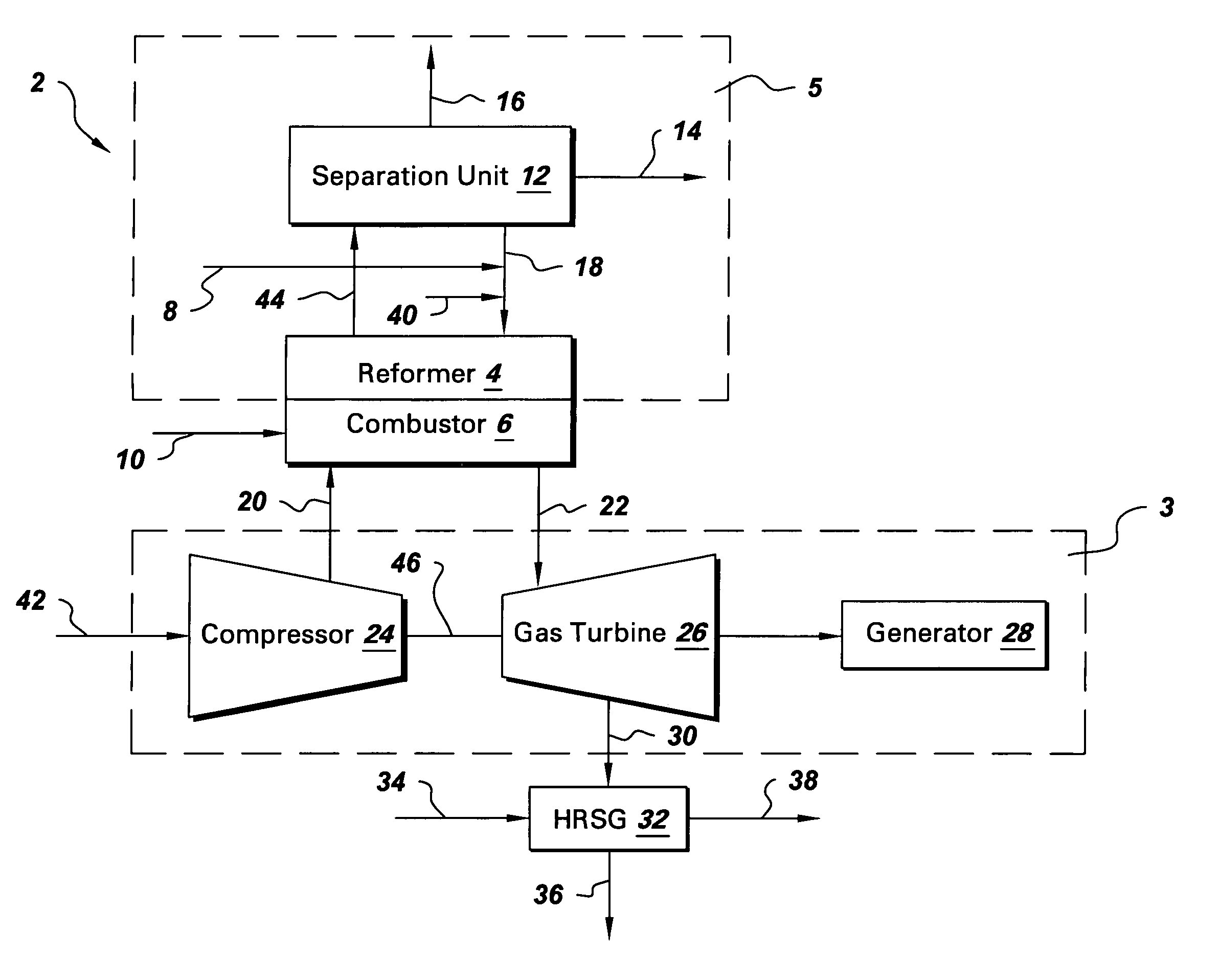
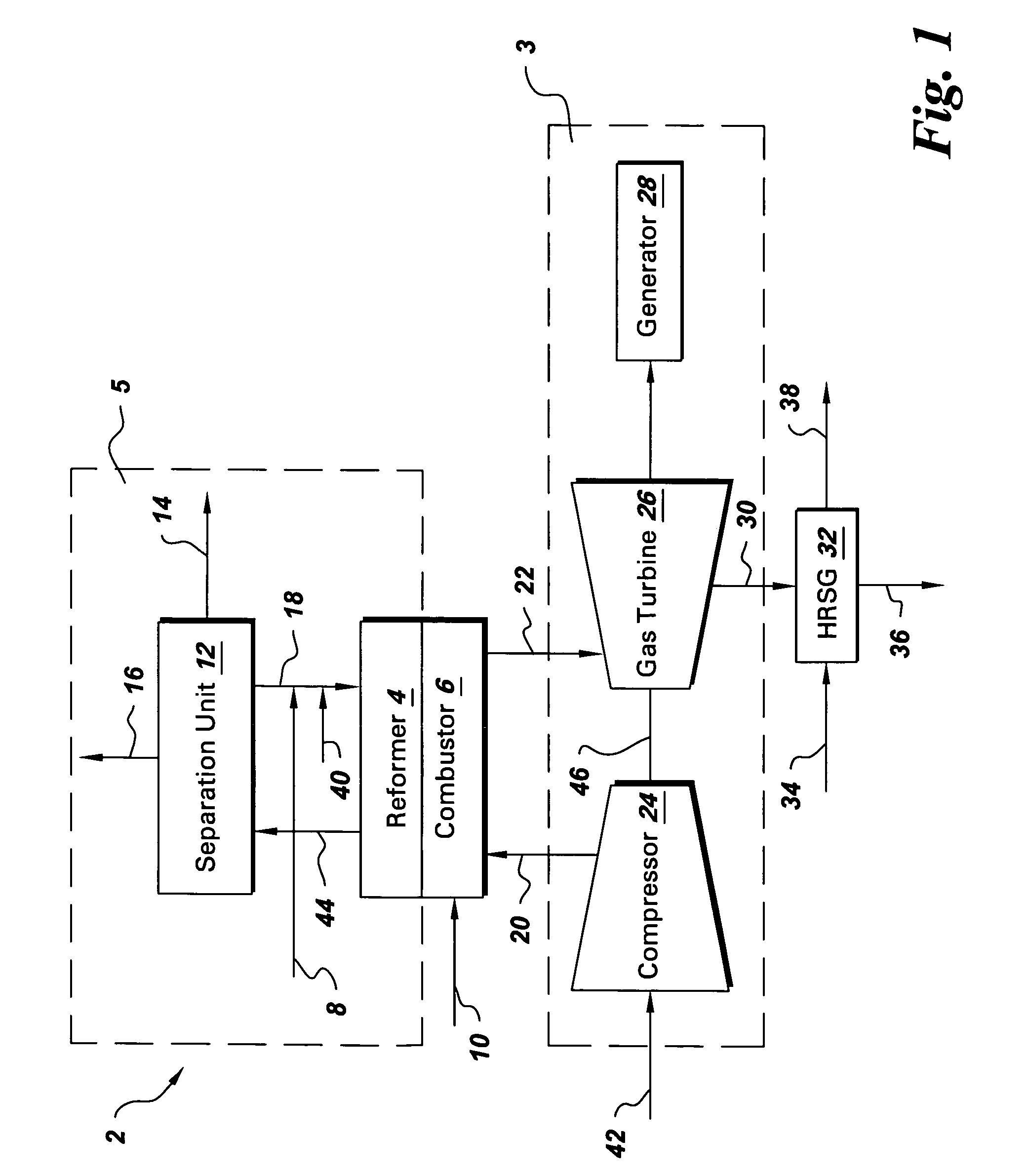
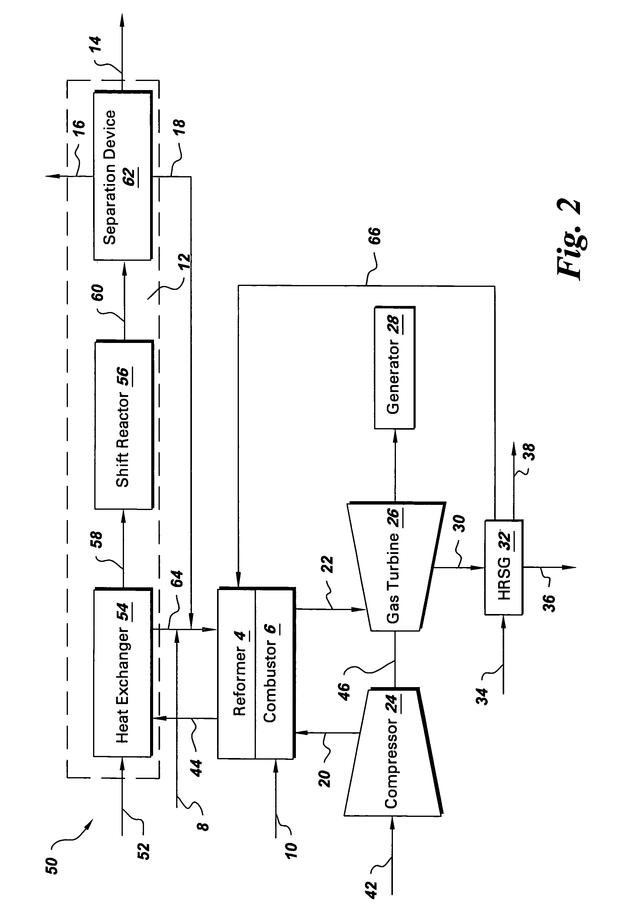
[0018]FIG. 1 schematically represents an exemplary co-production system 2 for producing hydrogen and electrical energy including a turbine portion 3 and a hydrogen generation portion 5. The hydrogen generation portion includes a reformer 4, and a separation unit 12. The turbine portion includes a combustor 6, a compressor 24, a gas turbine 26, and a rotor 46, by which rotor, turbine 26 drives the compressor 24. The reformer 4 is coupled with the combustor 6, wherein the heat of combustion from the combustor 6 is utilized in the reforming process in the reformer 4. As explained in some detail below, while the basic components of the co-production system 2 are mostly well known, efficiency improvements in relation to known systems are obtained through strategic interconnection of system components with recirculation flow paths to enhance performance and efficiency of the system. The efficiency of a co-production system is enhanced by recovering the energy from the exhaust streams from...


PUM

PropertyMeasurementUnit
temperatureaaaaaaaaaa
electricalaaaaaaaaaa

Abstract

A system for co-production of hydrogen and electrical energy comprising a reformer configured to receive a reformer fuel and steam and produce a reformate rich in hydrogen. The system further comprises a separation unit in fluid communication with the reformer wherein the separation unit is configured to receive the reformate to separate hydrogen from the reformate and produce an off gas. The system also includes a combustor configured to receive a fuel for combustion and produce heat energy and a hot compressed gas, wherein the combustor is coupled with the reformer. A gas turbine expands the hot compressed gas and produces electrical energy and an expanded gas; wherein at least a part of the heat energy from the combustor is used to produce the reformate in the reformer.

Description

BACKGROUND OF THE INVENTION[0001]The present invention relates to energy generation systems and more particularly to co-production of hydrogen and electrical energy.[0002]In recent years, various attempts have been made to use a combined cycle power generating system, in which system a fuel is burned in a combustor to produce a hot gas which hot gas drives a gas turbine to generate electrical power. The combustor in a combined cycle power generation system is typically cooled by compressed air, which compressed air is readily available in the plant. Using compressed air for cooling the combustor limits the lower limit of the flame temperature in the combustor, which in turn, may result in higher nitrous-oxide (NOx) production and emission.[0003]A co-production route typically produces electricity as well as some liquid fuel or chemical from the same feedstock. The concept of co-production is based on producing chemicals or liquid fuels during the lean electricity demand period and u...

Claims


Application Information

Patent Timeline
Patent Type & Authority Patents(United States)
IPC IPC(8): F02C6/18F01K23/10C01B3/34C01B3/38C01B3/50F02C3/22F02C6/00
CPCC01B3/34C01B3/50C01B2203/0233C01B2203/0283C01B2203/04C01B2203/0405C01B2203/0415C01B2203/042C01B2203/043C01B2203/047C01B2203/0475C01B2203/0811C01B2203/0822C01B2203/0827C01B2203/1294C01B2203/148C01B2203/86Y02E20/16Y02P20/10Y02P20/129Y02P30/00
Inventor BALAN, CHELLAPPACOLIBABA-EVULET, ANDREI
Owner GENERAL ELECTRIC CO
Why Eureka
Try Eureka