Deployable flap edge fence

a technology of flaps and edges, applied in the direction of influencers by generating vortices, airframe and engine noise, etc., can solve the problems of airframe noise being a much greater factor, engine noise being the most objectionable, and airframe noise being a large factor, so as to reduce drag, reduce fluid flow noise, and reduce airflow noise

Active Publication Date: 2010-07-13
THE BOEING CO
View PDF12 Cites 28 Cited by
  • Summary
  • Abstract
  • Description
  • Claims
  • Application Information

AI Technical Summary

Benefits of technology

[0008]A method and systems for reducing fluid flow noise using a deployable flap edge fence are proposed. The method shapes the deployable flap edge fence in response to a temperature change. In this regard, the method reduces airflow noise by thermally activating a deployable flap edge fence for approach and landing. With the flap edge fence deployed, vortices generated at the side edge of a flap are prevented from directly rolling over from the lower surface of the flap to the upper surface of the flap. The method also reduces drag by stowing the deployable flap edge fence for cruise thereby reducing interaction of the deployable flap edge fence with local air-flow over the body.
[0012]A further embodiment includes an adaptive fluid dynamic system for reducing drag / fluid noise due to fluid flow. The system includes: a body capable of generating lift by moving through a fluid, and a deployable body edge fence coupled to the body. A control mechanism is used to reconfigure the body edge fence into a deployed state for a first set of operating conditions, and to reconfigure the body edge fence again into a stowed state for a second set of operating conditions.

Problems solved by technology

An airplane's airframe and engines produce varying amounts of objectionable audible noise during different flight conditions.
During departure, the engines produce most of the noise; however, during approach, airframe noise is a much greater factor.
Airframe noise is generated by air flowing over the airplane's fuselage, landing gear, wing leading and trailing edges equipped with high-lift devices and flap systems.
Therefore, airframe noise has become a more dominant source of aerosound, and particularly so for an airplane during approach to landing.
These two vortex systems dither around the surrounding surfaces, emitting broadband noise.
At some angle-of-attack dependent chord-wise location, the lower vortex core will spill over the sharp top surface edge 108 creating additional broadband noise.
As shown in FIG. 2, the two vortex-systems then entrain each other and develop into a high-intensity tightly formed vortex core 214 which can be detrimental for airplanes crossing the wake further downstream
One of the problems facing the successful installation of such a flap edge fence is that, while highly beneficial with a fully extended flap system, the fences are far from optimal in high-speed cruise conditions.
This would result in wasted lifting forces and additional drag, which in turn creates unnecessary loads on the structure.
Currently, existing flap edge fences are fixed and no alternatives are available.

Method used


Image

  • Deployable flap edge fence
  • Deployable flap edge fence
  • Deployable flap edge fence

Examples


Embodiment Construction

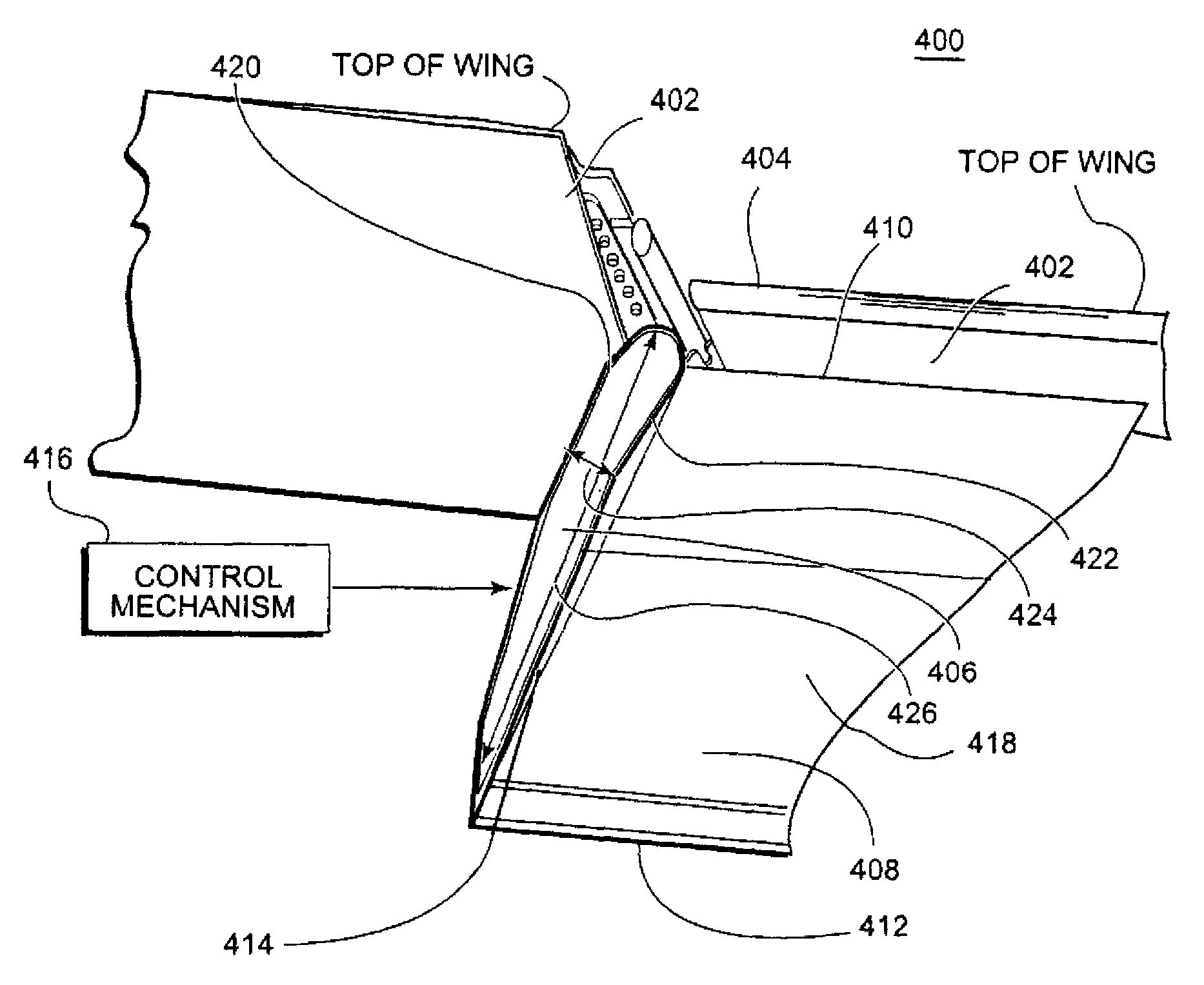
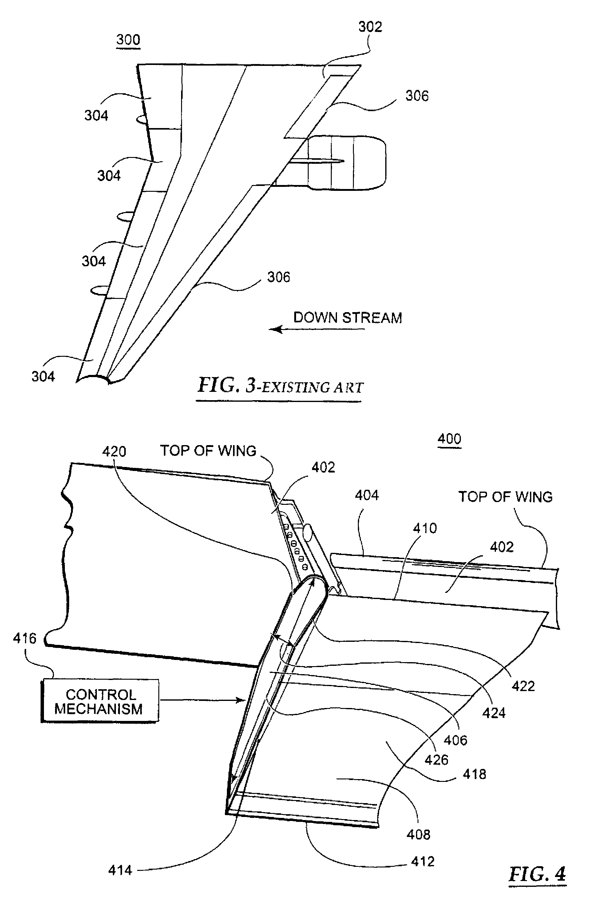
[0027]The following detailed description is merely illustrative in nature and is not intended to limit the embodiments of the disclosure nor the application and uses of such embodiments. Furthermore, there is no intention to be bound by any expressed or implied theory presented in the preceding technical field, background, brief summary or the following detailed description.

[0028]Embodiments of the disclosure may be described herein in terms of functional and / or logical block components and various processing steps. It should be appreciated that such block components may be realized by any number of hardware, software, and / or firmware components configured to perform the specified functions. For the sake of brevity, conventional techniques and components related to signal processing, aircraft control systems, high lift devices, and other functional aspects of the systems (and the individual operating components of the systems) may not be described in detail herein. In addition, thos...


PUM


Abstract

A method and systems are disclosed for reducing fluid flow noise. The method and systems use a thermal mechanism to deploy a flap edge fence during landing and / or other operating conditions, and stow the flap edge fence during other operational conditions such as cruise. The flap edge fence is controlled passively by ambient temperature or actively by a controller based on temperature changes corresponding to various operating conditions.

Description

TECHNICAL FIELD[0001]Embodiments of the present disclosure relate generally to reducing noise produced by fluid dynamic surfaces moving in a fluid. More particularly, embodiments of the present disclosure relate to a deployable flap edge fence for an aircraft for reducing airflow noise (aerosound) produced by a flap edge when it is exposed to the fluid (e.g. air) during certain flight conditions.BACKGROUND[0002]An airplane's airframe and engines produce varying amounts of objectionable audible noise during different flight conditions. During departure, the engines produce most of the noise; however, during approach, airframe noise is a much greater factor. Airframe noise is generated by air flowing over the airplane's fuselage, landing gear, wing leading and trailing edges equipped with high-lift devices and flap systems. On the approach to landing, high lift systems, such as wing leading edge devices and wing trailing edge flap systems, are extended and the engines are operated at ...

Claims


Application Information

Patent Timeline
Patent Type & Authority Patents(United States)
IPC IPC(8): B64C23/06
CPCB64C7/00B64C9/18B64C9/24B64C23/06Y02T50/162Y02T50/32Y02T50/10Y02T50/30
Inventor LARSSEN, JON V.CALKINS, FREDERICK T.
Owner THE BOEING CO
Why Eureka
Try Eureka