Route planning system for agricultural working machines

a technology for agricultural working machines and planning systems, applied in navigation instruments, distance measurement, instruments, etc., can solve problems such as inability to take into account large number of combine harvesters, system not being able to state a reasonable unloading position, and system not being able to meet the needs of large-scale harvesting

Active Publication Date: 2010-07-13
CLAAS SELBSTFAHRENDE ERNTEMASCHINEN GMBH
View PDF14 Cites 71 Cited by
  • Summary
  • Abstract
  • Description
  • Claims
  • Application Information

AI Technical Summary

Benefits of technology

[0005]The task of the present invention, therefore, is to avoid the disadvantages of the related art and provide a route planning system which takes changing external conditions into account in a flexible manner.

Problems solved by technology

Systems of this type have the particular disadvantage that they determine the particular unloading position based on fixedly predefined driving routes of the route planning system.
If the combine harvester deviates from these predefined driving routes, e.g., to avoid obstacles, the system is no longer capable of stating a reasonable unloading position, since the combine harvester subsequently travels along driving routes that the route planning system does not know.
In addition, systems of this type do not permit interactions between a large number of combine harvesters and the unloading vehicles assigned to them.
The main disadvantage of such systems is that the geometric position of the likely unloading point is determined soley based on the throughput and / or grain fill level which were determined, and that geographic conditions of the field are not taken into account.
As a result, it is possible that a point on the field will be determined to be the unloading position, but it will not be possible to move the unloading vehicle into this position relative to the combine harvester.
In these cases, the coordination function fails, and the drivers of the machines must determine their positions in a conventional manner, i.e., by sight.

Method used


Image

  • Route planning system for agricultural working machines
  • Route planning system for agricultural working machines
  • Route planning system for agricultural working machines

Examples


Embodiment Construction

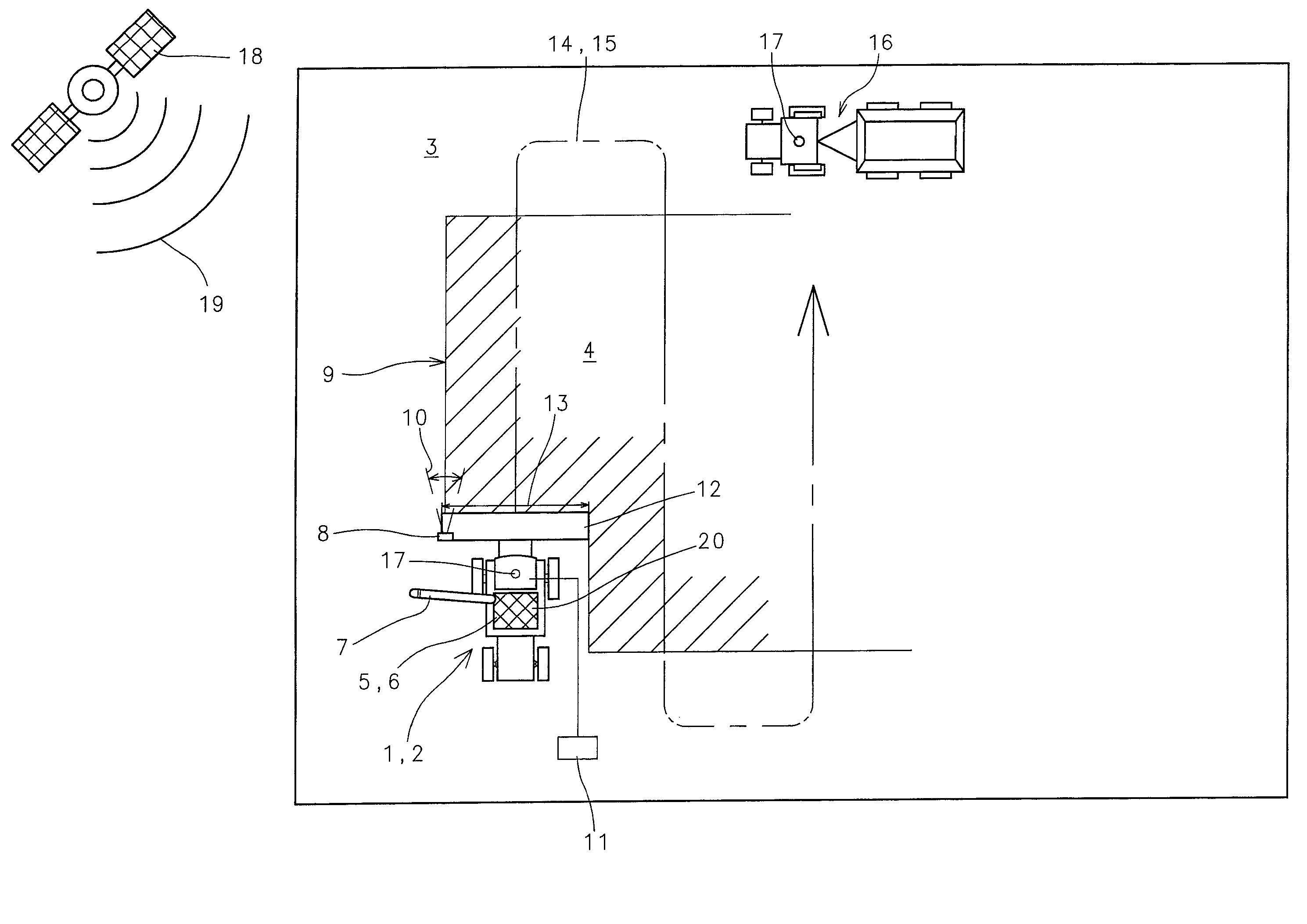
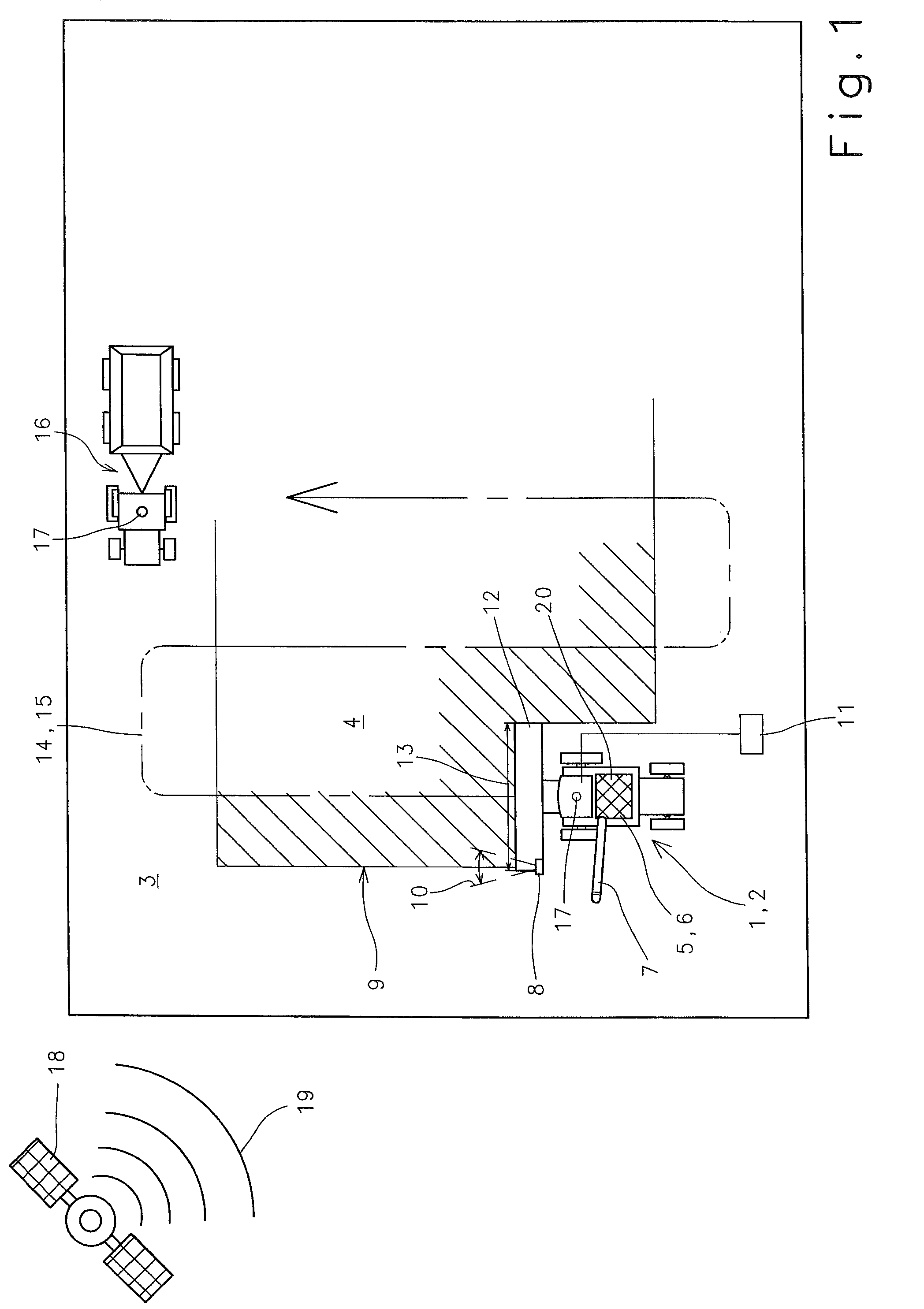
[0026]FIG. 1 shows an agricultural working machine 1 designed as a combine harvester 2 as it harvests a crop 4 which is growing on a territory 3 to be worked. In a manner known per se, combine harvester 2 includes a crop material storage unit 6 which is designed as a grain tank 5 and stores the harvested corn, and an unloading device 7, via which grain tank 5 can be emptied. A crop edge detection device 8 is assigned to the front of combine harvester 2, which detects crop edge 9 of crop 4 to be harvested. In a manner known per se, crop edge detection device 8 can be designed as a laser sensor, the oscillating detection beam 10 of which generates a depiction of the position of crop edge 9 in an evaluation unit 11 assigned to combine harvester 2 and, with consideration for working width 13 of combine harvester 2 determined by the width of front attachment 12, generates driving routes 14 for the inventive route planning system 15, which will be described in greater detail.

[0027]To empt...


PUM


Abstract

A route planning system for an agricultural working machine including at least one crop material storage unit for storing quantities of crop material transferable to forage vehicles, has a unit for generating driving routes in a territory based on a defined working width assigned to the agricultural working machine, a unit for reconciling a crop material quantity stored in the crop material storage unit depending on at least one characteristic parameter, and a unit for dynamically adapting the reconciliation to changes in the at least one characteristic parameter.

Description

CROSS-REFERENCE TO A RELATED APPLICATION[0001]The invention described and claimed hereinbelow is also described in German Patent Application DE 10 2005 059 003.9 filed on Dec. 8, 2005. This German Patent Application, whose subject matter is incorporated here by reference, provides the basis for a claim of priority of invention under 35 U.S.C. 119(a)-(d).BACKGROUND OF THE INVENTION[0002]The present invention relates to a route planning system for agricultural working machines.[0003]Publication DE 196 29 618 makes known a route planning system for combine harvesters, which, in the route plan that was determined, displays the positions of the combine harvester at which the grain tank of the combine harvester will probably be filled. To determine the grain tank fill level, the information is evaluated by throughput and fill level sensors, and the point in time when the grain tank will be completely filled is approximated with consideration for the grain tank volume. Systems of this type...

Claims


Application Information

Patent Timeline
Patent Type & Authority Patents(United States)
IPC IPC(8): G01C21/00G01C21/30G01C22/00
CPCA01B69/007A01D41/127A01D91/00G05D1/024G05D1/0278G05D1/0219G05D2201/0201
Inventor DIEKHANS, NORBERTBRUNNERT, ANDREAS
Owner CLAAS SELBSTFAHRENDE ERNTEMASCHINEN GMBH
Why Eureka
Try Eureka