Convergent divergent nozzle with slot cooled nozzle liner

a divergent nozzle and divergent technology, applied in the direction of vessel construction, marine propulsion, aircraft navigation control, etc., can solve the problems of difficult coating processing and maintenance, limited strength of nb, and low efficiency of nb procurement, so as to minimize thermal cycling, facilitate sealing, and mitigate the necessity of exotic alloys

Active Publication Date: 2010-07-20
RTX CORP
View PDF60 Cites 16 Cited by
  • Summary
  • Abstract
  • Description
  • Claims
  • Application Information

AI Technical Summary

Benefits of technology

[0009]Each cooling liner panel includes an arcuate cooling liner leading edge which interfaces with an aft cooling liner seal land wall of the cooling liner main body assembly. The arcuate cooling liner leading edge provides a cam interface which facilitates a seal during nozzle system articulation. The arcuate cooling liner leading edge includes a multiple of openings which are rectilinear slot shaped openings to distribute cooling airflow over both the inner “cold-side” and outer “hot-side” surfaces of the cooling liner panel. Through this backside cooling of the cooling liner panels thermal gradients are controlled at the attachment interface between the arcuate cooling liner leading edge and the main cooling liner body. The provision of a smooth film cooling boundary layer of the cooling airflow minimizes thermal cycling and mitigates the necessity of exotic alloys in this area of the convergent section.
[0010]The present invention therefore provides effective cooling of a cooling liner main body convergent section interface with materials which are less expansive to manufacture yet provide increased durability.

Problems solved by technology

However, Nb may have limited strength and may require difficult to process and maintain coatings.
Raw material costs and current lead-time for procurement of Nb is also relatively significant.

Method used


Image

  • Convergent divergent nozzle with slot cooled nozzle liner
  • Convergent divergent nozzle with slot cooled nozzle liner
  • Convergent divergent nozzle with slot cooled nozzle liner

Examples


Embodiment Construction

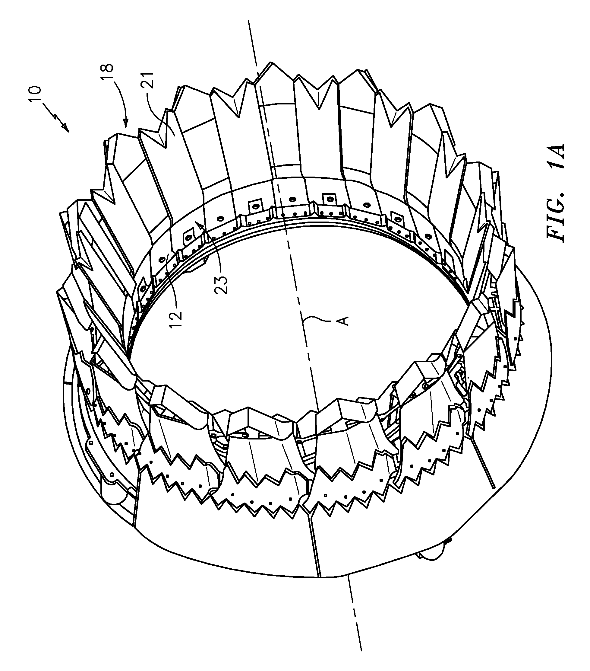
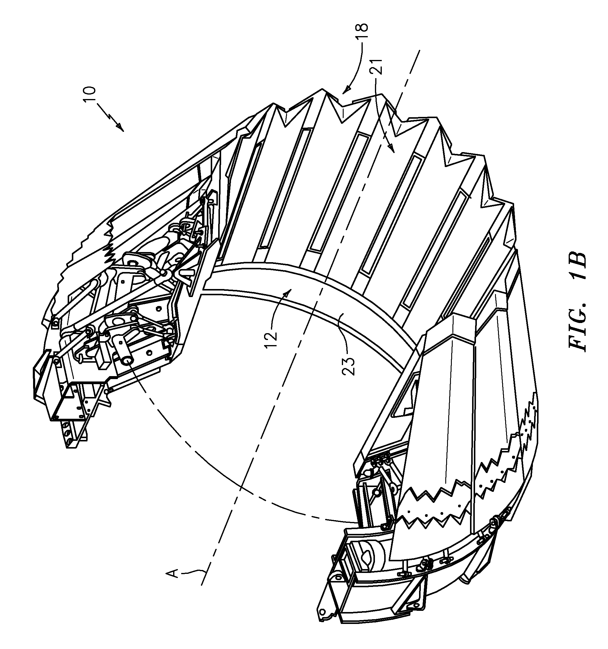
[0022]FIGS. 1A and 1B illustrate an axi-symetric high degree of motion (HDM) nozzle system 10 for a gas turbine engine. FIG. 1A depicts the nozzle 10 in a maximum dilated position relative a nozzle centerline A (also illustrated in cross-section FIG. 2A), which is typical during afterburning operation, and FIG. 1B depicts the nozzle system 10 in a minimal dilated position relative the nozzle centerline A (FIG. 2B), which is typical during non-afterburning operation.

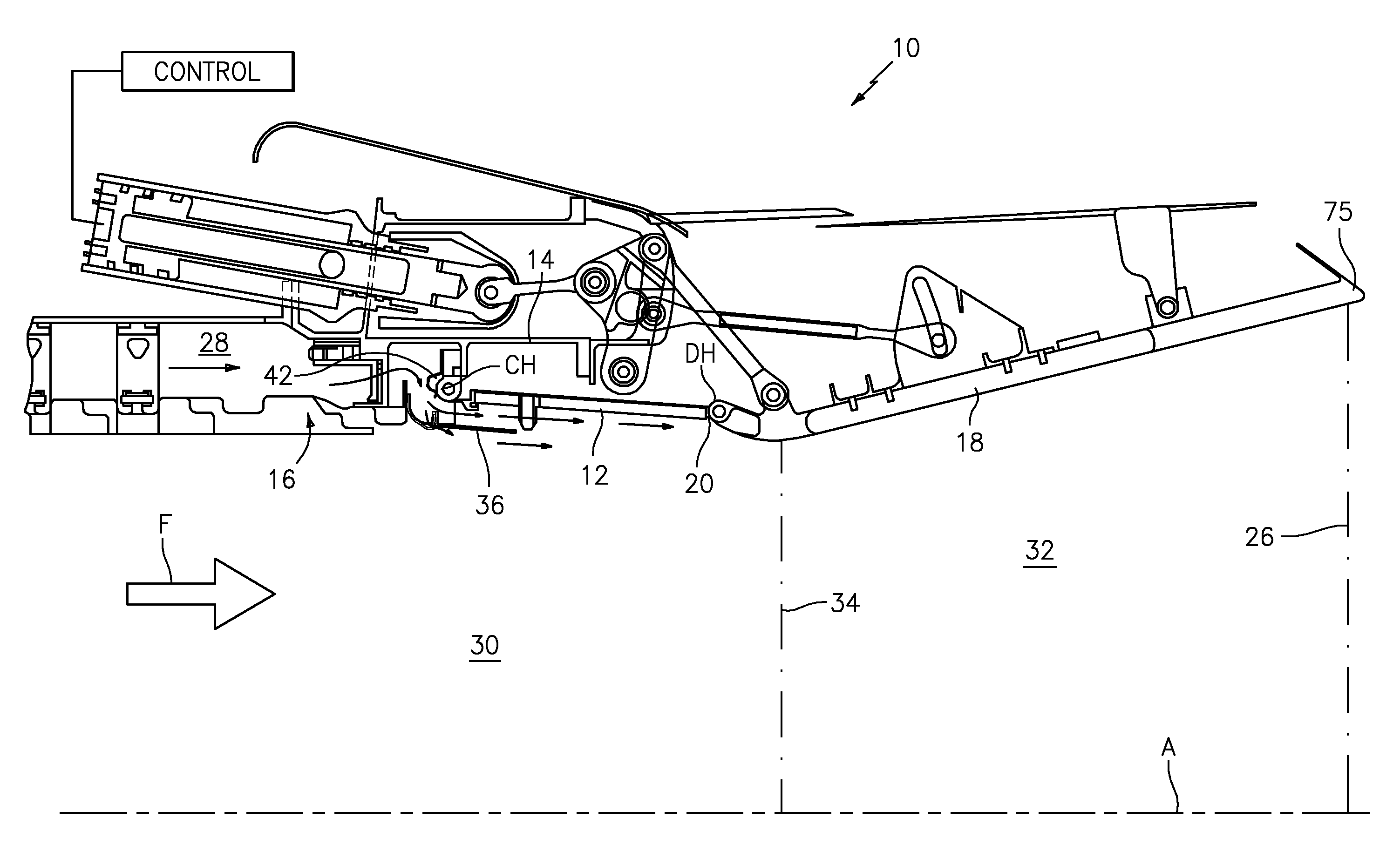
[0023]Referring to FIGS. 2A and 2B, the nozzle includes a plurality of circumferentially distributed convergent flaps 12 (only one shown in section), each pivotably connected to a stationary structure 14 at a convergent section hinge line Ch having a cooling liner body 16 upstream thereof. A plurality of circumferentially distributed divergent flaps 18 (only one shown in section) are pivotably connected at a convergent joint structure 20 to an aft end section of the convergent flaps 12.

[0024]A plurality of divergent seals...


PUM


Abstract

A nozzle system includes a multitude of circumferentially distributed convergent flaps and seals that circumscribe an engine centerline. A cooling liner body cooperates with a cooling liner panel attached to respective convergent flaps and convergent seals to define an annular cooling airflow passageway which is movable therewith. Each cooling liner panels includes an arcuate cooling liner leading edge with a multiple of openings to distribute cooling airflow over both the inner “cold-side” and outer “hot-side” surfaces thereof. Through this backside cooling, thermal gradients are controlled at the attachment interface between the arcuate cooling liner leading edge and the main cooling liner body.

Description

[0001]This invention was made with government support under Contract No. N00019-02-C-3003 with the Department of Navy. The government therefore has certain rights in this invention.BACKGROUND OF THE INVENTION[0002]The present invention relates to gas turbine engines having convergent / divergent nozzles, and more particularly to a cooled divergent seal arrangement.[0003]An exhaust nozzle optimizes the thrust produced within a gas turbine engine. In augmented gas turbine engines, convergent / divergent (C / D) nozzles provide a multitude of nozzle positions. Flaps circumferentially distributed aft of the augmentor or exhaust duct form the convergent and divergent sections for which the nozzle is named. Flap seals disposed between adjacent flaps minimize gas leakage between flaps in both sections. The convergent section is pivotally connected to the augmentor or exhaust duct and to the divergent section. The divergent section is pivotally connected to the convergent section and to an extern...

Claims


Application Information

Patent Timeline
Patent Type & Authority Patents(United States)
IPC IPC(8): F02K99/00F02K1/00B05B1/24B63H11/10
CPCF02K1/1223F02K1/822Y02T50/675Y02T50/60
Inventor KEHRET, DEBORA F.FARAH, JORGE I.
Owner RTX CORP
Why Eureka
Try Eureka