
Microbubble generating device and hair washing device utilizing the same

a technology of generating device and hair washing, which is applied in the direction of gas purification by liquid washing, flow mixer, packaged goods type, etc., can solve the problems of difficulty in sufficient washing, and achieve the effect of effective cleaning

Inactive Publication Date: 2010-07-20
SHIGEN KAIHATSU
View PDF20 Cites 5 Cited by
  • Summary
  • Abstract
  • Description
  • Claims
  • Application Information

AI Technical Summary

Benefits of technology

"The present invention provides a bubble generating device that can generate uniform microbubbles. This device includes a source of water, a dissolving water making unit, and a bubble generating unit. The gas dissolving device sucks gas and makes dissolved water by mixing water and gas. The bubble generating unit generates microbubbles from the dissolved water. The invention also provides a hair washing device that uses the bubble generating device to effectively clean hair by removing dirt and debris from the scalp. The technical effects of the invention include the ability to generate fine bubbles, remove excess gas, and make uniform bubbles in the dissolved water."

Problems solved by technology

In the hair washing device, a shower is merely sprayed on the head, and therefore has a problem that it is difficult to sufficiently wash, for example, the scalp.

Method used


Image

  • Microbubble generating device and hair washing device utilizing the same
  • Microbubble generating device and hair washing device utilizing the same
  • Microbubble generating device and hair washing device utilizing the same

Examples


Embodiment Construction

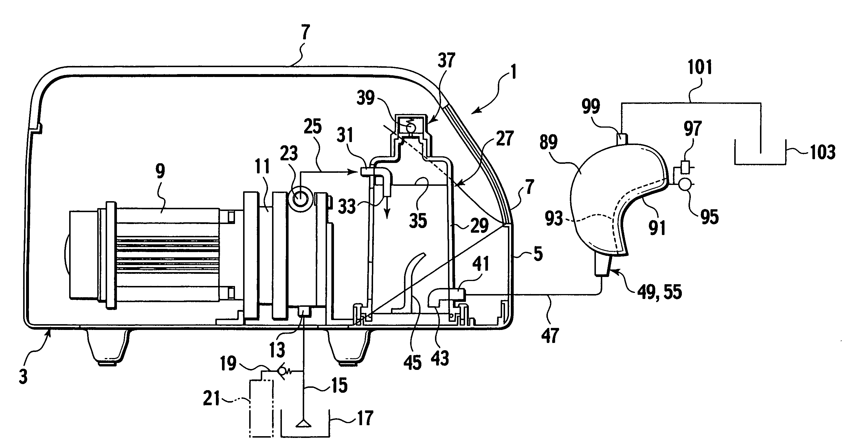
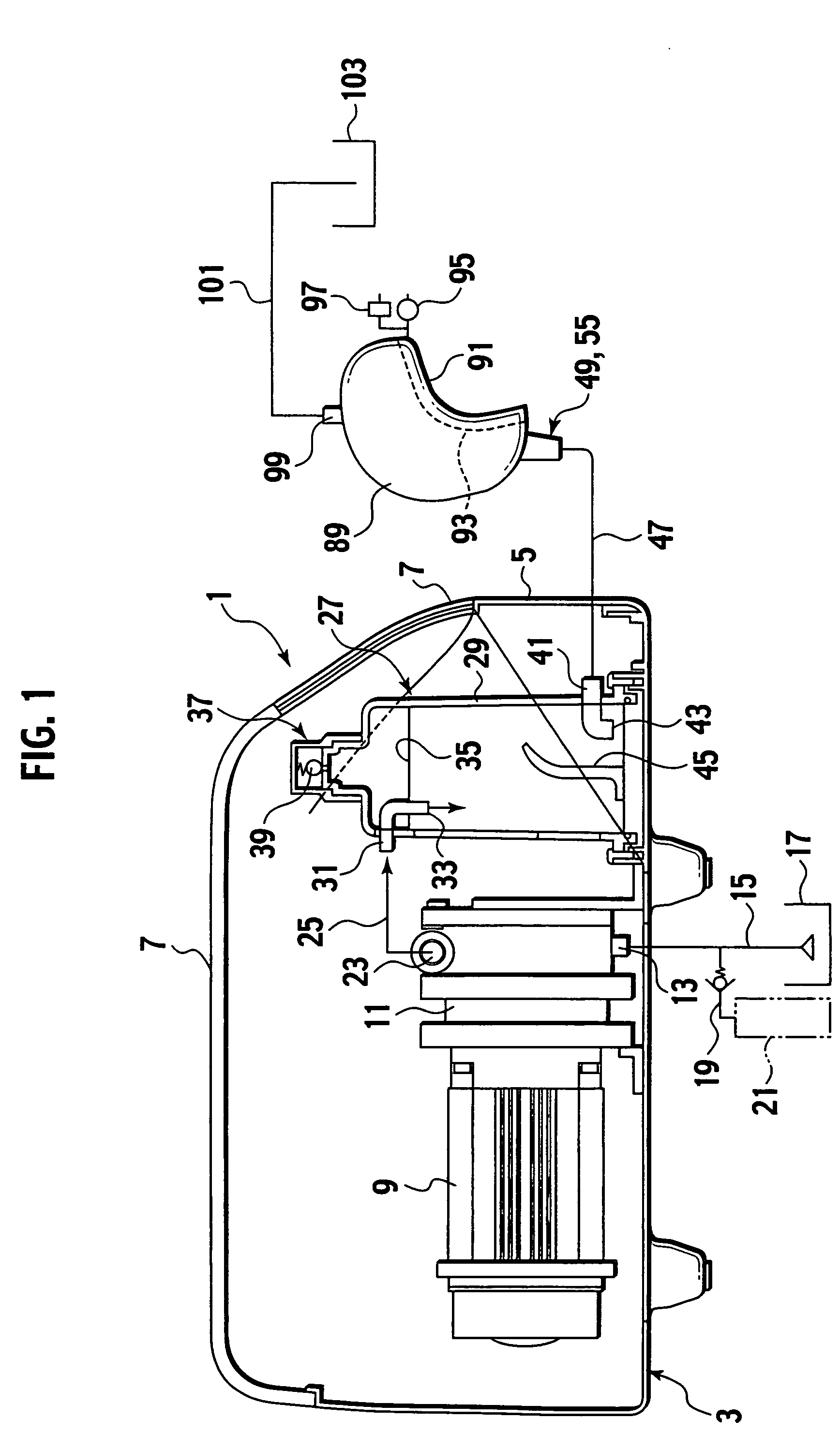
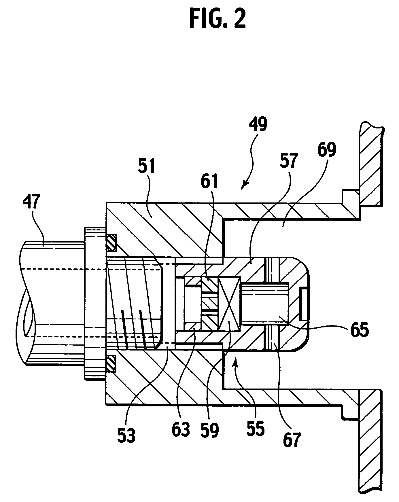
[0025]Hereinafter, an embodiment of the present invention will be described with reference to the drawings. In the description below of the drawings, the identical or similar components are denoted by the identical or similar reference numerals. It should be noted, however, that the drawings are schematic, and that the relationship between thicknesses and plane dimensions, the proportions of the thicknesses of layers and the like differ from those of actual ones. In addition, the embodiment described below exemplifies an device for embodying technical principles of the present invention. The technical principles of the present invention do not limit the materials, shapes, structures, arrangement, and the like, of components to undermentioned ones. The technical principles of the present invention allow various modifications to be made within the scope of claims.

[0026]As shown in FIG. 1, a microbubble generating device 1 according to the embodiment of the present invention includes a...


PUM

PropertyMeasurementUnit
diametersaaaaaaaaaa
momentumaaaaaaaaaa
pressureaaaaaaaaaa

Abstract

A dissolving water making unit and a bubble generating unit are provided. The dissolving water making unit includes a gas dissolving device for dissolving gas in water. The bubble generating unit includes a bubble generating nozzle and a bubble generating cartridge. The dissolving water making unit sucks water from a water source, and sucks gas to make dissolving water from a mixed solution in which the water and the gas are mixed together. The dissolving water is obtained by dissolving the gas in the water. The bubble generating unit generates microbubbles from the dissolving water supplied from the dissolving water making unit. The gas dissolving device includes a closed vessel; an inflow port which is provided in the closed vessel, and which is provided for causing the mixed liquid sucked from the source to flow into the closed vessel; an exhaust valve which is provided in an upper portion of the closed vessel, and which is provided for exhausting excess gas from the mixed liquid; and an outflow port which is provided near a bottom portion of the closed vessel, and which is provided for causing the dissolving water to flow out from the closed vessel to the bubble generating unit. Between the inflow port and the outflow port, the closed vessel has a retention region in which the dissolving water flows slowly, in which air is dissolved in the dissolving water to substantial saturation, and in which the dissolving water hardly contains fine bubbles.

Description

CROSS-REFERENCE TO RELATED APPLICATION[0001]This application is based upon and claims the benefit of priority from the prior Japanese Application No. 2005-327849, filed on Nov. 11, 2005; the entire contents of which are incorporated herein by reference.BACKGROUND OF THE INVENTION[0002]1. Field of the Invention[0003]The present invention relates to a microbubble generating device for generating microbubbles having diameters of approximately 1 μm to 50 μm, and relates to a hair washing device utilizing the microbubble generating device.[0004]2. Description of the Related Art[0005]In Japanese Patent Application Laid-open Publication No. 2003-265938, a microbubble generating device sucks water in a bathtub using a pump. Thereafter, using a compressor, the device presses air into water which is transported under pressure by the pump. Accordingly, a mixed liquid, in which water and the air are mixed together, is made. Then, the microbubble generating device introduces the mixed liquid int...

Claims


Application Information

Patent Timeline
Patent Type & Authority Patents(United States)
IPC IPC(8): B01F3/04
CPCA45D19/14B01F3/0446B01F3/04985B01F5/0682B01F5/0694A45D19/10A45D44/06Y10S261/75B01F23/232B01F23/2373B01F23/29B01F25/45231B01F25/45B01F23/2326
Inventor TAKAHASHI, TSUNEJIROOKUMURA, TOSHITAKAKUBO, KOICHI
Owner SHIGEN KAIHATSU
Learn More