Vibration damper

a vibration damper and damper technology, applied in the field of vibration dampers, can solve the problems of inability to meet the requirements of durability, the above-described conventional vibration damper using rubber or a coil spring suffers, and the durability of hard rubber unavoidably needs to be used in actual practice in view of durability, so as to achieve superior durability and high vibration damping

Inactive Publication Date: 2010-07-20
HITACHI LTD
View PDF11 Cites 5 Cited by
  • Summary
  • Abstract
  • Description
  • Claims
  • Application Information

AI Technical Summary

Benefits of technology

[0007]The present invention has been made in view of the above-described circumstances. Accordingly, an object of the present invention is to provide a vibration damper, isolator or absorber exhibiting high vibration damping, isolating or absorbing performance and at the same time having superior durability.

Problems solved by technology

The above-described conventional vibration damper using rubber or a coil spring suffers, however, from the following problems.
If soft rubber is used, vibration damping performance can be improved, but durability degrades.
Therefore, rather hard rubber unavoidably needs to be used in actual practice in view of durability.
Accordingly, satisfactory vibration damping performance cannot be obtained.
When the vibration amplitude of the compressor becomes large at the time of starting or stopping the compressor or when the load changes, the vibration damper using soft rubber may fail to provide a satisfactory vibration damping effect.
Therefore, a pipe, hose, electric cable, etc. that are connected to the compressor and so forth are constantly under the influence of vibration and hence likely to be deteriorated.
In addition, vibration may have an adverse effect on the compressor and other equipment.
The above-described problems are common to all equipment having an on-board fluid pump such as a pump that supplies a fluid pressure to a brake system mounted on an automobile, a vacuum pump that supplies a negative pressure to a booster used in a brake system, or a hydraulic pump that supplies a fluid pressure to a power steering system.

Method used


Image

  • Vibration damper
  • Vibration damper
  • Vibration damper

Examples


first embodiment

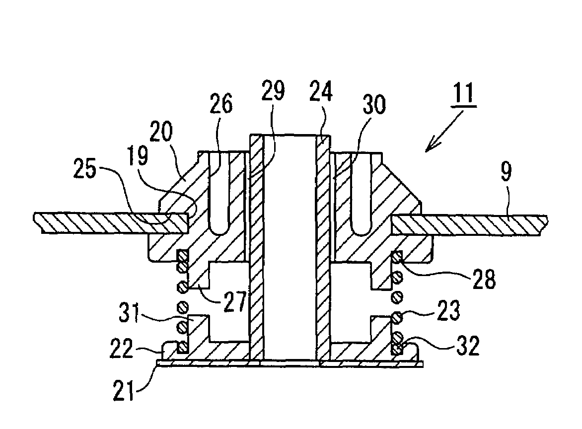
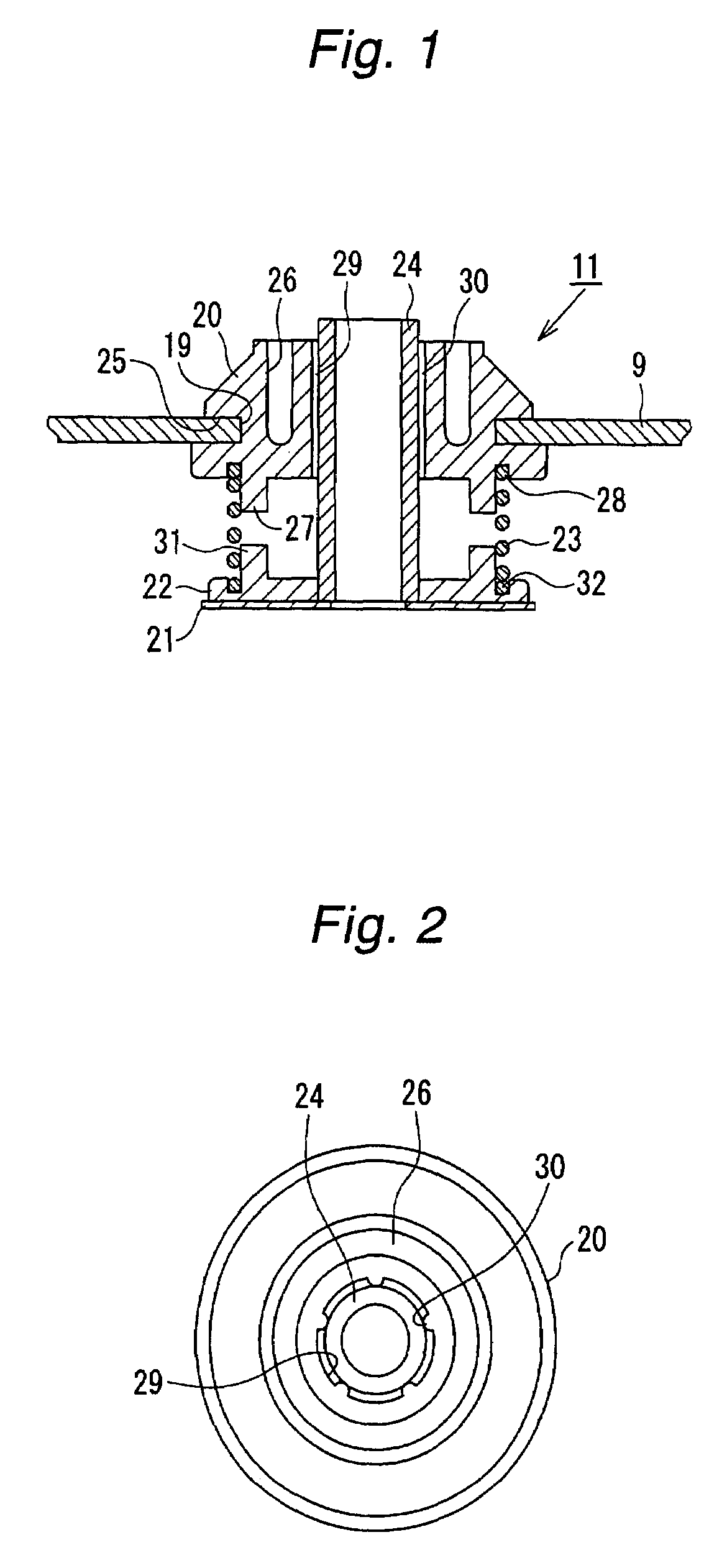
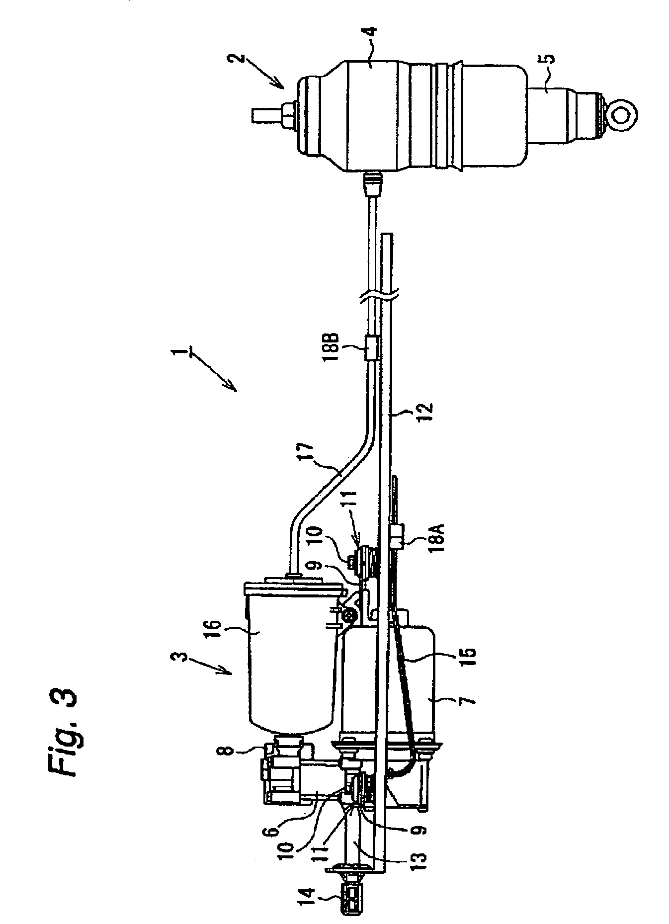
[0020]the present invention will be described with reference to FIGS. 1 to 3.

[0021]An automotive air-suspension system to which a vibration damper according to this embodiment is applied will be explained with reference to FIG. 3. As shown in FIG. 3, an air-suspension system 1 has an air suspension 2 interposed between a sprung member and an unsprung member, i.e. between the vehicle body and a suspension member that supports a wheel, and a compressor unit 3 (first member) for supplying and exhausting compressed air to and from the air suspension 2.

[0022]The air suspension 2 comprises an air spring 4 and a shock absorber 5 that are integrated into one unit. The air spring 4 is a suspension spring that supports the vehicle body by the spring force thereof. The air spring 4 is supplied with and exhausted of compressed air by the compressor unit 3, thereby allowing vehicle height control to be effected. The shock absorber 5 damps vibration between the sprung and unsprung members.

[0023]T...


PUM


Abstract

An upper bush is secured to a bracket of a compressor unit, and a lower bush is abutted against a panel member of a vehicle body through a washer. A coil spring is interposed between the upper and lower bushes. A pipe member is inserted through the upper and lower bushes and the coil spring. A bolt is inserted through the pipe member and screwed into the panel member of the vehicle body. The compressor unit is resiliently supported floatingly by the coil spring. Vibration of the compressor unit is damped by friction generated by sliding contact between the pipe member and raised portions of the upper bush. When the vibration amplitude is large, respective projections of the upper and lower bushes abut against each other to suppress the vibration while absorbing impact.

Description

BACKGROUND OF THE INVENTION[0001]1. Technical Field[0002]The present invention relates to a vibration damper, isolator or absorber for use in an automotive air-suspension system having a compressor unit for vehicle height control to suppress the transmission of vibration from a vibration source such as a compressor to a mounting part such as a vehicle body where the compressor unit is secured.[0003]2. Description of Related Art[0004]Among automotive suspension systems are air-suspension systems capable of performing vehicle height control by supplying and exhausting compressed air to and from an air spring by using a compressor. An air-suspension system is provided with a vibration damper so that vibration of the compressor in operation is not transmitted to the vehicle body. A conventional vibration damper provided in an air-suspension system has rubber or a coil spring interposed between a vibration source such as a compressor and a vehicle body, thereby suppressing the transmissi...

Claims


Application Information

Patent Timeline
Patent Type & Authority Patents(United States)
IPC IPC(8): B60G11/52
CPCF16F1/128F16F7/08
Inventor YAMA, KAZUHISAITOU, TSUTOMU
Owner HITACHI LTD
Why Eureka
Try Eureka