Multiple scan-plane ultrasound imaging of objects

a scanning plane and ultrasound imaging technology, applied in the field of real-time ultrasound imaging, can solve problems such as limited practical use of solutions, and achieve the effect of slow delay

Active Publication Date: 2010-07-20
ANGELSEN BJORN A J +1
View PDF28 Cites 32 Cited by
  • Summary
  • Abstract
  • Description
  • Claims
  • Application Information

AI Technical Summary

Benefits of technology

[0008]The invention presents methods for practically real time ultrasound imaging of objects in 3 or more 2D ultrasound scan planes, where the 2D scan-planes are rotated around a common axis. With practically real time is here meant that the image data is collected along a set of sample beams within said 2D scan planes, and the sample beam data collection occurs so frequently of the object that all the sample beam data defining the image is collected within so short time period in relation to movements of the object, that the collected data captures a for practical purposes frozen frame the moving object. The image data can in addition be displayed on an image screen with so slow delay that one for practical purposes can view the object as it moves.
[0010]The invention further presents detailed designs of ultrasound transducer arrays that allows sector scanning of an ultrasound beam in three or four 2D scan planes that are rotated around a common axis. The design is composed of at least two active piezoelectric, phased array transducer layers mounted face to face in a sandwich structure that is mounted on a backing material. The piezoelectric sandwich front face is connected to the load material through a set of elastic impedance interfacing layers for improving the acoustic power coupling between the piezoelectric layers and the load material. In a special wide band design, the impedance interfacing layer closest to the piezoelectric layers has the same characteristic impedance as the piezoelectric layers, as described in [5].
[0013]Transmitting a wide beam and covering it with several narrow receive beams in parallel, one can increase the frame rate by a factor of order 2-6. Other increase in the frame rate is obtained by reducing the beam density where the scan planes intersect, and where the beams have limited information about the object, for example internal in the left ventricle while the ventricular walls are covered with high density of beams for ventricular wall motion analysis. For special high frame rate observation of the heart in the different scan planes, one can keep the same scan plane direction for a whole cardiac cycle, and change direction of the scan plane right before the onset of the myocardial contraction, for example triggered by the ECG signal from the heart.
[0014]The invention also shows a special embodiment where the multi-scan plane phased array is mounted at the tip of an endoscope for imaging of objects from internal in the body. In particular, such a method is useful for transesophageal imaging of the heart in many scan planes, for example to assist anesthesia monitoring during surgery. The transesophageal array can further be rotated mechanically in the endoscope for detailed alignment of the scan planes with interesting areas, or to increase the number of scan planes that are imaged.

Problems solved by technology

A phased array transducer for electronic selection of the ultrasound scan planes in two angular directions has been presented in [1], but this solution has found limited practical use, mainly because one wants to observe the object in more than two planes, generally at least three or four angular directions of the 2D scan plane.

Method used


Image

  • Multiple scan-plane ultrasound imaging of objects
  • Multiple scan-plane ultrasound imaging of objects
  • Multiple scan-plane ultrasound imaging of objects

Examples


Embodiment Construction

[0029]Several example embodiments according to the invention is presented in the following. It is clear that this presentation is meant for illustration purposes only, and by no means represents limitations of the invention, which in its broadest aspect is defined by the claims appended hereto.

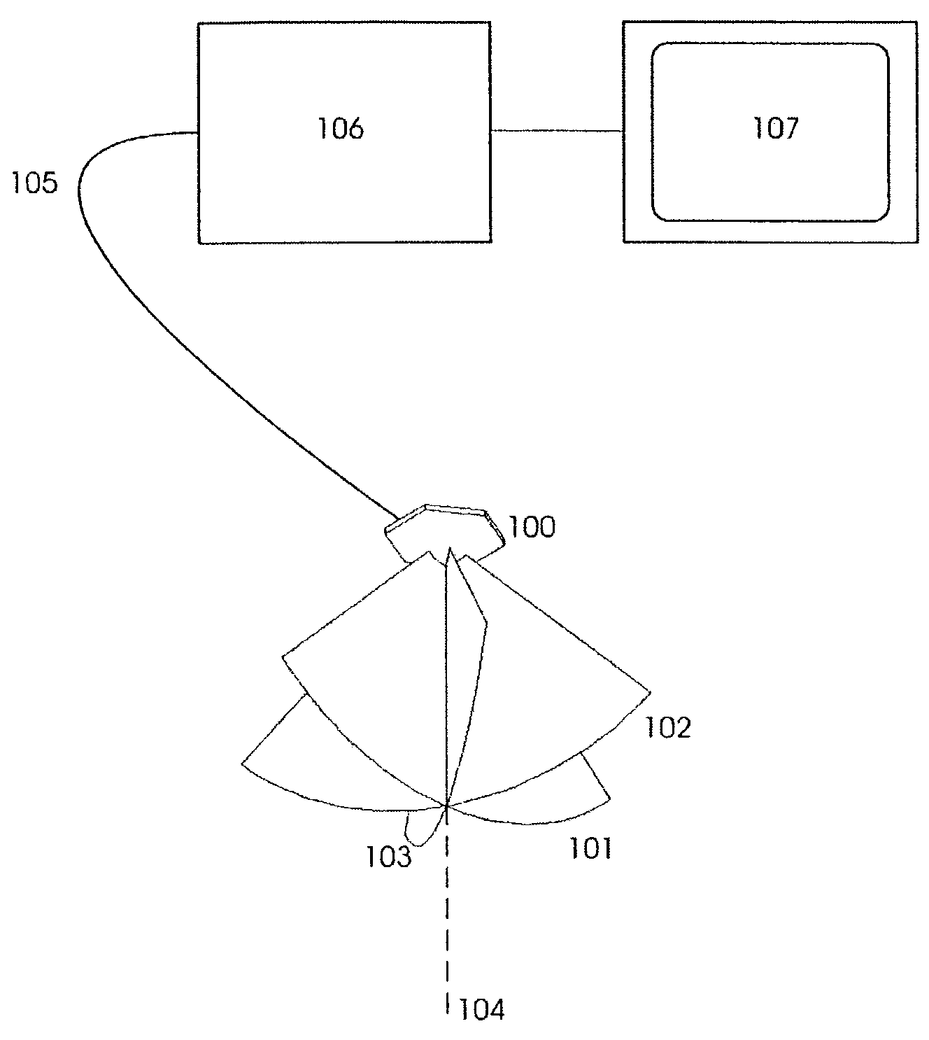
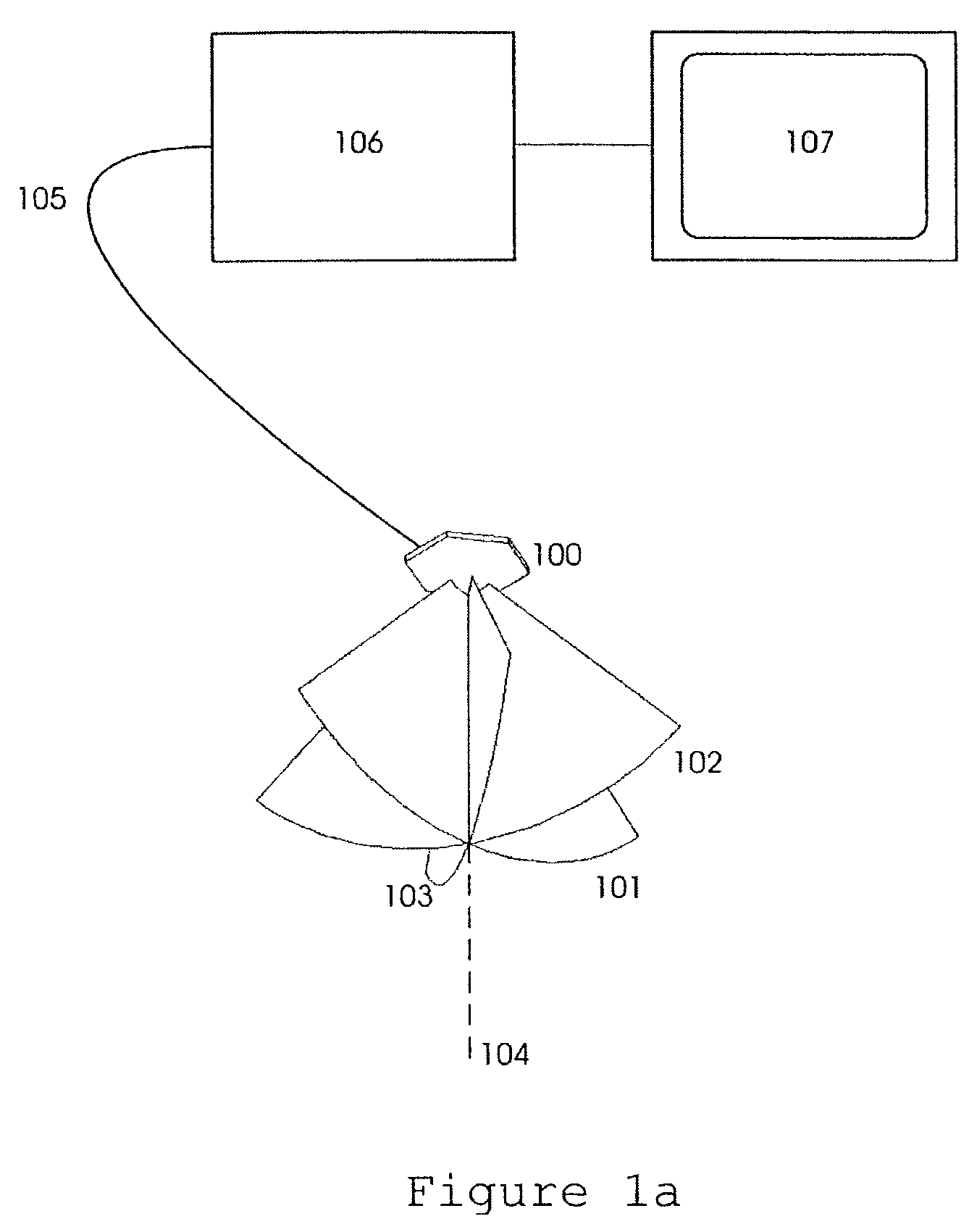
[0030]As an example embodiment of the invention, FIG. 1a shows a transducer array 100 that is capable of transmitting pulsed ultrasound beams with directions freely and electronically steerable within for example three 2D sector scan planes 101, 102, and 103, that are rotated with different angular directions around a common axis 104. The transducer array is connected via a cable 105 to an ultrasound imaging instrument 106 with image outputs given to a display screen 107.

[0031]In a typical imaging situation, the ultrasound imaging instrument 106 directs signals to the transducer that transmit ultrasound beams in selected directions within the 2D scan planes 101-103. The back scattered signal i...


PUM


Abstract

A method of real time ultrasound imaging of an object in at least three two-dimensional scan planes that are rotated around a common axis, is given, together with designs of ultrasound transducer arrays that allows for such imaging. The method is also introduced into a monitoring situation of cardiac function where, combined with other measurements as for example the LV pressure, physiological parameters like ejection fraction and muscular fiber stress is calculated.

Description

PRIORITY CLAIM[0001]Priority is claimed for this invention and application, corresponding application(s) having been filed in US on Mar. 15, 2002, No. 60 / 364,747.BACKGROUND OF THE INVENTION[0002]1. Field of the Invention[0003]The present invention is directed to real time ultrasound imaging of an object, like a biological structure, in multiple scan planes. Designs of efficient ultrasound phased array bulk wave transducers for two-dimensional ultrasound imaging, with several, electronically selectable 2D scan planes, are given. The electronic selection of the 2D scan plane direction allows so rapid switching of the direction that practically real time observation of moving objects like the heart, can be obtained simultaneously in several scan planes. The invention also addresses real time ultrasound monitoring of the cardiac function.[0004]2. Description of the Related Art[0005]In medical ultrasound imaging, one often examines an object through a variety of two-dimensional (2D) scan...

Claims


Application Information

Patent Timeline
Patent Type & Authority Patents(United States)
IPC IPC(8): A61B8/00A61B8/06G01S7/52A61B8/08G01S15/89H01L41/08H01L41/09H04R17/00
CPCA61B8/06A61B8/13A61B8/145G01S15/8925G01S7/52074G01S15/8927
Inventor ANGELSEN, BJORN A. J.JOHANSEN, TONNI F.
Owner ANGELSEN BJORN A J
Why Eureka
Try Eureka