
Fuel cell

a fuel cell and fuel cell technology, applied in the field of fuel cells, can solve the problems of reactant gas not flowing smoothly, unsatisfactory sealing performance, and unsatisfactory sealing performance, and achieve the effect of simple and economical structure and effective simplifying the process of assembling the fuel cell

Active Publication Date: 2010-07-20
HONDA MOTOR CO LTD
View PDF4 Cites 1 Cited by
  • Summary
  • Abstract
  • Description
  • Claims
  • Application Information

AI Technical Summary

Benefits of technology

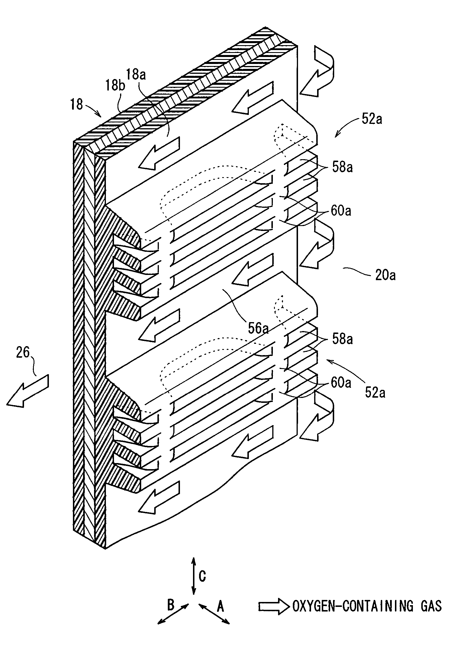
The present invention provides a fuel cell with a simple and economical structure that can effectively simplify the assembly process. The fuel cell includes an electrolyte electrode assembly and a metal separator with a rubber wall member that divides the fluid flow field and the fluid passage. The rubber wall member has a groove formed by a cutout in the stacking direction and a partition closing at least part of the groove to prevent fluid flow. This design increases the elasticity of the rubber wall member and ensures tight contact between the metal separator and adjacent components, achieving the desired sealing performance. The partition provides reliable supply of fluid and ensures desired power generation and cooling performance.

Problems solved by technology

However, at the time of tightening the separator and the electrolyte electrode assembly, and a seal member between the separator and the electrolyte electrode assembly, the seal member enters the connection channels undesirably.
Thus, the desired sealing performance cannot be maintained, and the reactant gas does not flow smoothly.
Thus, operation of attaching the SUS plates 7 is laborious.
In particular, in the case where several tens to several hundreds of fuel cells are stacked together, the process of attaching the SUS plates 7 is considerably complicated, and time consuming.
Thus, the cost of fabricating the fuel cells is significantly high.

Method used


Image

  • Fuel cell
  • Fuel cell
  • Fuel cell

Examples


first embodiment

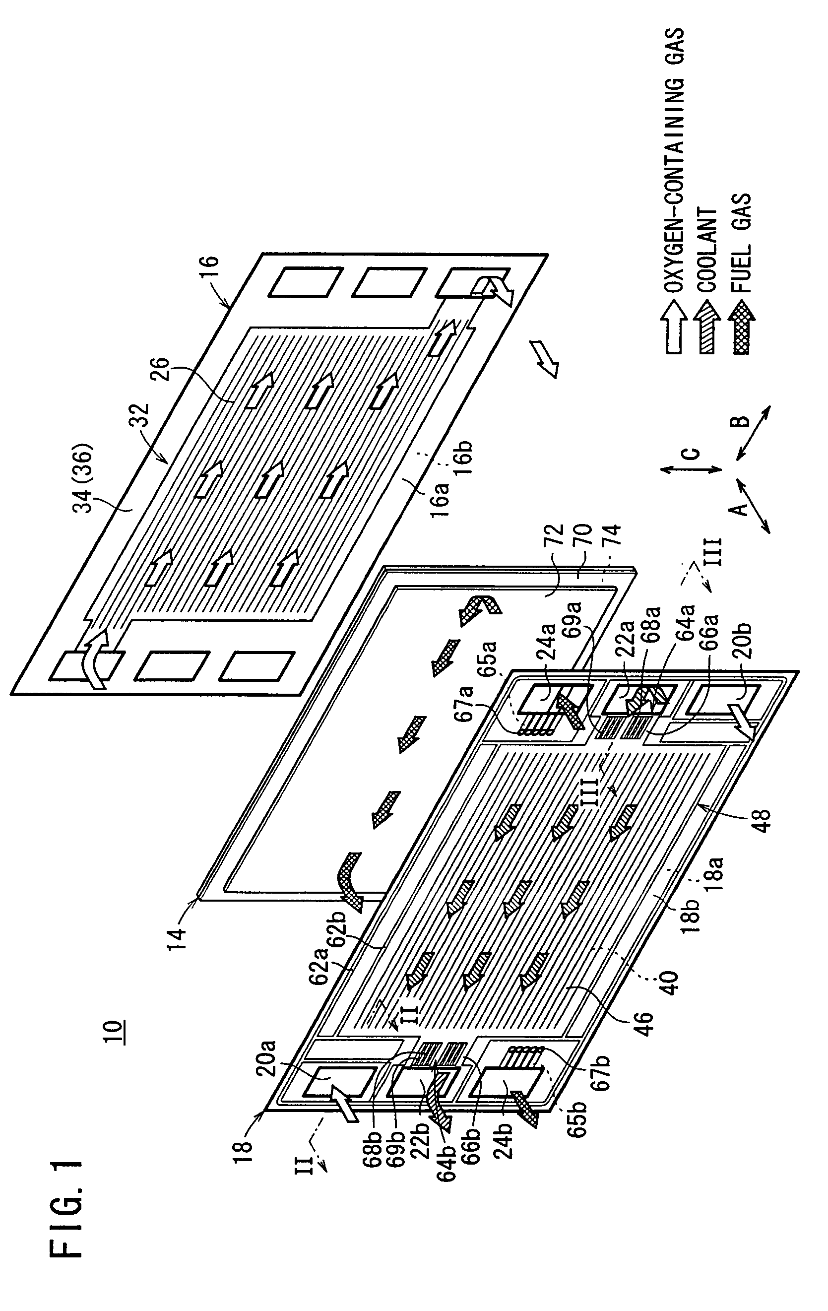
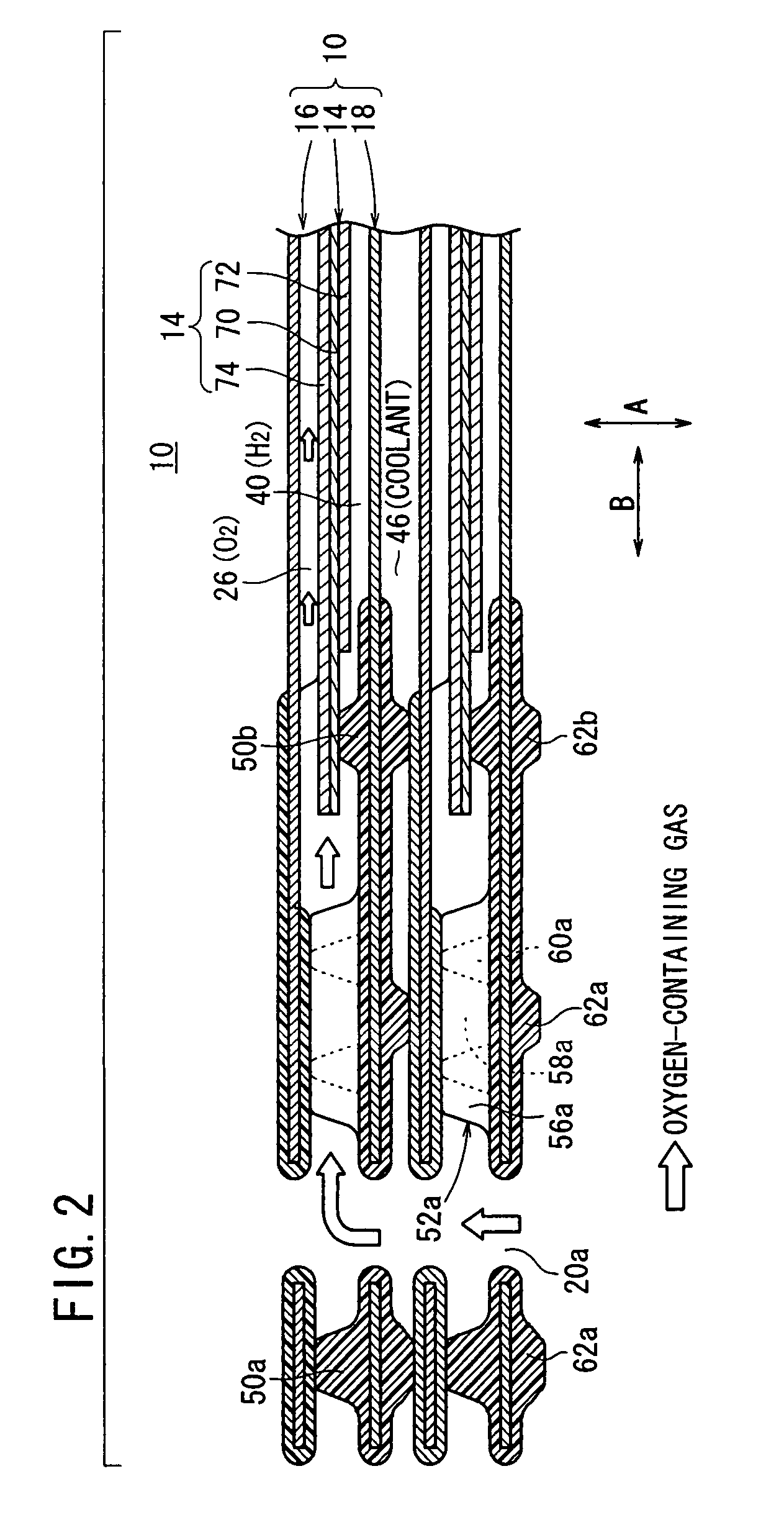
[0031]FIG. 1 is an exploded perspective view showing main components of a fuel cell 10 according to the present invention. FIG. 2 is a cross sectional view showing a fuel cell stack 12 formed by stacking a plurality of the fuel cells 10, taken along a line II-II in FIG. 1. FIG. 3 is a cross sectional view showing the fuel cell stack 12, taken along a line III-III in FIG. 1.

[0032]As shown in FIG. 1, each of the fuel cells 10 includes a membrane electrode assembly (electrolyte electrode assembly) 14 and a first metal separator 16 and a second metal separator 18 sandwiching the membrane electrode assembly 14. For example, the first metal separator 16 and the second metal separator 18 are steel plates, stainless steel plates, aluminum plates, or plated steel plates.

[0033]At one end of the fuel cell 10 in a horizontal direction indicated by an arrow B, an oxygen-containing gas supply passage 20a for supplying an oxidant gas such as an oxygen-containing gas, a coolant discharge passage 22...

third embodiment

[0072]FIG. 10 is a view showing one surface 18a of a second metal separator 90 of a fuel cell according to the present invention.

[0073]Rubber bridges (rubber wall members) 92a, 92b are provided near the oxygen-containing gas supply passage 20a and the oxygen-containing gas discharge passage 20b, respectively. In effect, the rubber bridges 92a, 92b are divided into three parts by a plurality of channels 56a, 56b. A plurality of grooves 94a, 94b are formed between the channels 56a, 56b. The grooves 94a, 94b are narrower than the channels 56a, 56b. Partitions 96a, 96b are provided in the rubber bridges 92a, 92b for closing the grooves 94a, 94b at one upstream end in the fluid flow direction to prevent the flow of the oxygen-containing gas (see FIGS. 10 and 11).

[0074]Though not shown, the rubber bridges 92a, 92b are provided on the surface 18b of the second metal separator 90 instead of the rubber bridges 64a, 64b.

fourth embodiment

[0075]FIG. 12 is a view showing one surface 18a of a second metal separator 100 of a fuel cell according to the present invention.

[0076]Rubber bridges (rubber wall members) 102a, 102 are formed on the surface 18a of the second metal separator 100 near the oxygen-containing gas supply passage 20a and the oxygen-containing gas discharge passage 20b, respectively. In effect, the bridges 102a, 102b are divided into three parts by a plurality of channels 56a, 56b. A plurality of grooves 104a, 104b are formed between the channels 56a, 56b. The grooves 104a, 104b are narrower than the channels 56a, 56b. A pair of partitions 106a, 106b are provided in the rubber bridges 102a, 102b. The partitions 106a 106b close the grooves 104a, 104b at both ends in the fluid flow direction to prevent the flow of the oxygen-containing gas (see FIGS. 12 and 13).

[0077]Though not shown, the rubber bridges 102a, 102b are provided on the surface 18b of the second metal separator 100 instead of the rubber bridge...


PUM

PropertyMeasurementUnit
timeaaaaaaaaaa
pressure lossaaaaaaaaaa
sizeaaaaaaaaaa

Abstract

A coolant flow field is formed on a surface of a second metal separator. Further, a rubber bridge dividing the coolant flow field and a coolant supply passage is formed on the surface. The rubber bridge includes a plurality of channels connecting the coolant flow field and the coolant supply passage, a plurality of grooves between the channels, and a partition closing the grooves to prevent the flow of a coolant in the respective grooves.

Description

BACKGROUND OF THE INVENTION[0001]1. Field of the Invention[0002]The present invention relates to a fuel cell formed by stacking an electrolyte electrode assembly and a metal separator in a stacking direction. The electrolyte electrode assembly includes a pair of electrodes and an electrolyte interposed between the electrodes. A fluid passage extends through the fuel cell in a stacking direction for supplying a fluid comprising at least one of a fuel gas, an oxygen-containing gas, and a coolant in the stacking direction.[0003]2. Description of the Related Art[0004]For example, a polymer electrolyte fuel cell employs a power generation cell formed by sandwiching a membrane electrode assembly (MEA) between separators. The membrane electrode assembly includes an anode, a cathode, and an electrolyte membrane interposed between the anode and the cathode. In use, normally, a predetermined number of power generation cells are stacked together to form a fuel cell stack.[0005]In the fuel cell...

Claims


Application Information

Patent Timeline
Patent Type & Authority Patents(United States)
IPC IPC(8): H01M8/04H01M2/14
CPCH01M8/0206H01M8/0228H01M8/0258H01M8/0267H01M8/0263H01M8/0284H01M8/04029H01M2008/1095Y02E60/50H01M8/241H01M8/2483H01M8/0276
Inventor GOTO, SHUHEINUNOKAWA, KAZUOTAKESHITA, TAKAHIROTAKAHASHI, KENSUGITA, NARUTOSHITANAKA, HIROYUKI
Owner HONDA MOTOR CO LTD
Learn More