Solid electrolytic capacitor and method of manufacturing the same

a technology capacitors, which is applied in the direction of electrolytic capacitors, liquid electrolytic capacitors, variable capacitors, etc., can solve the problem of increasing the equivalent series resistance (esr) of solid electrolytic capacitors, and achieve the effect of smaller equivalent series resistance and large capacity

Inactive Publication Date: 2010-07-20
SANYO ELECTRIC CO LTD
View PDF8 Cites 17 Cited by
  • Summary
  • Abstract
  • Description
  • Claims
  • Application Information

AI Technical Summary

Benefits of technology

[0011]The inventors have carefully examined why the smaller particle diameter increases the equivalent series resistance of the solid electrolytic capacitor. The followings are new findings from our careful examination. In a case where particles of a metal or alloy to be used for the sintering process are made smaller in diameter, the smaller particle diameter increases contacts among metal particles. The increased contacts increase the electrical resistance inside the sintered body. In addition, because the smaller particle diameter narrows down spaces among the metal particles, this narrowness decreases the film thickness of the conducting polymer layer as the electrolytic layer formed among the metal particles. In this manner, when the particles of the metal or alloy to be used for the sintering process are made smaller in diameter, the smaller particle diameter increases the electrical resistance.
[0012]For the purpose of solving the foregoing problem, a solid electrolytic capacitor provides a structure including a thicker conducting polymer layer which is formed among metal particles by making larger the metal particles inside the anode body and achieves a lower electrical resistance. Further provided is a structure where the spaces among the metal particles in the outer periphery of the anode body are narrowed. Narrowing the spaces checks the oxidant from drying unevenly between the inside and the outer periphery of the anode body, in an oxidant adhering and drying process employed while monomers for conducting polymer are being polymerized. As a result, the adhesive properties and a coverage factor of the conducting polymer inside the anode body is improved.

Problems solved by technology

However, when particles of a metal or alloy to be used for the sintering process are made smaller in diameter, the smaller particle diameter brings about a problem of increasing the equivalent series resistance (ESR) of the solid electrolytic capacitor.

Method used


Image

  • Solid electrolytic capacitor and method of manufacturing the same
  • Solid electrolytic capacitor and method of manufacturing the same
  • Solid electrolytic capacitor and method of manufacturing the same

Examples


first embodiment

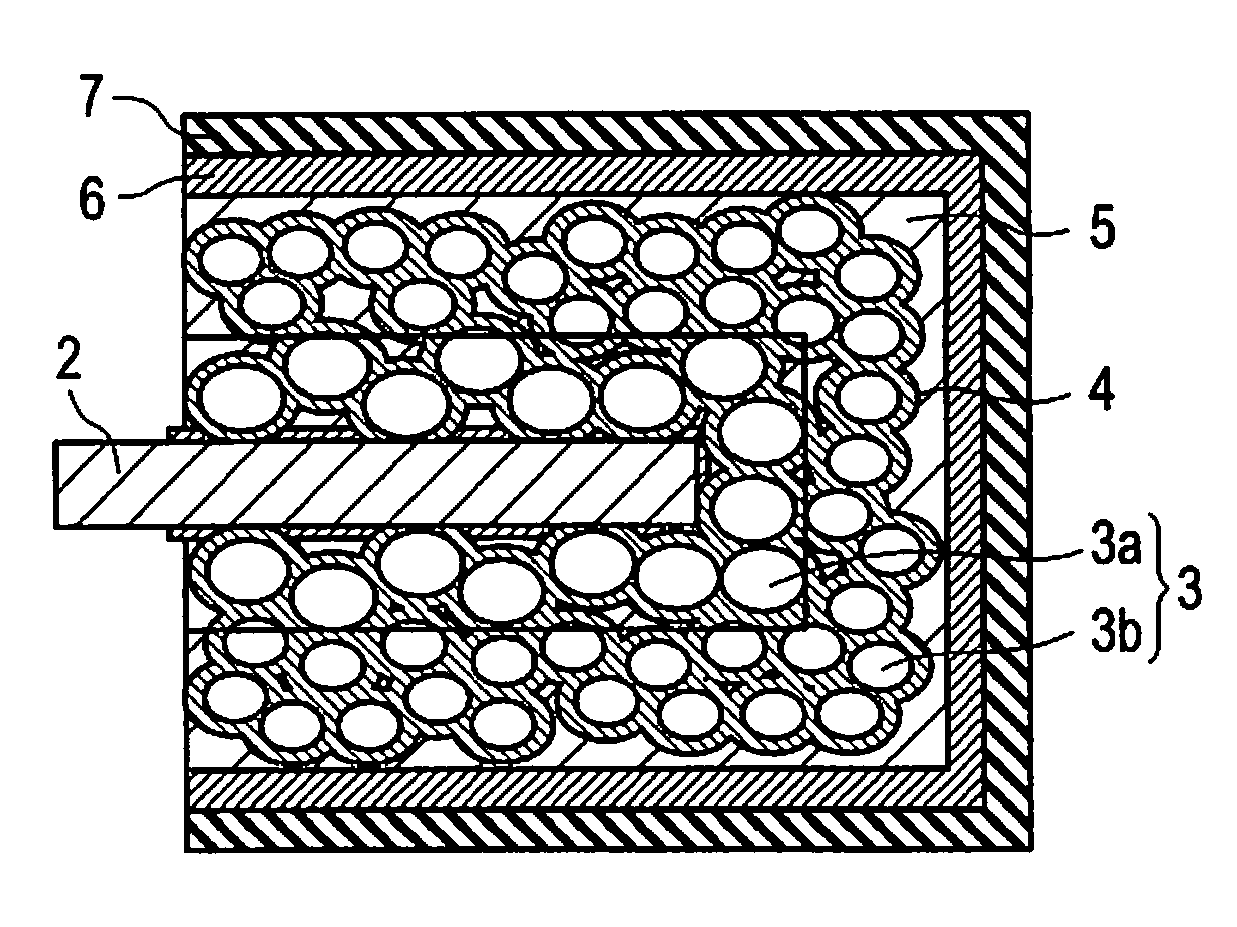
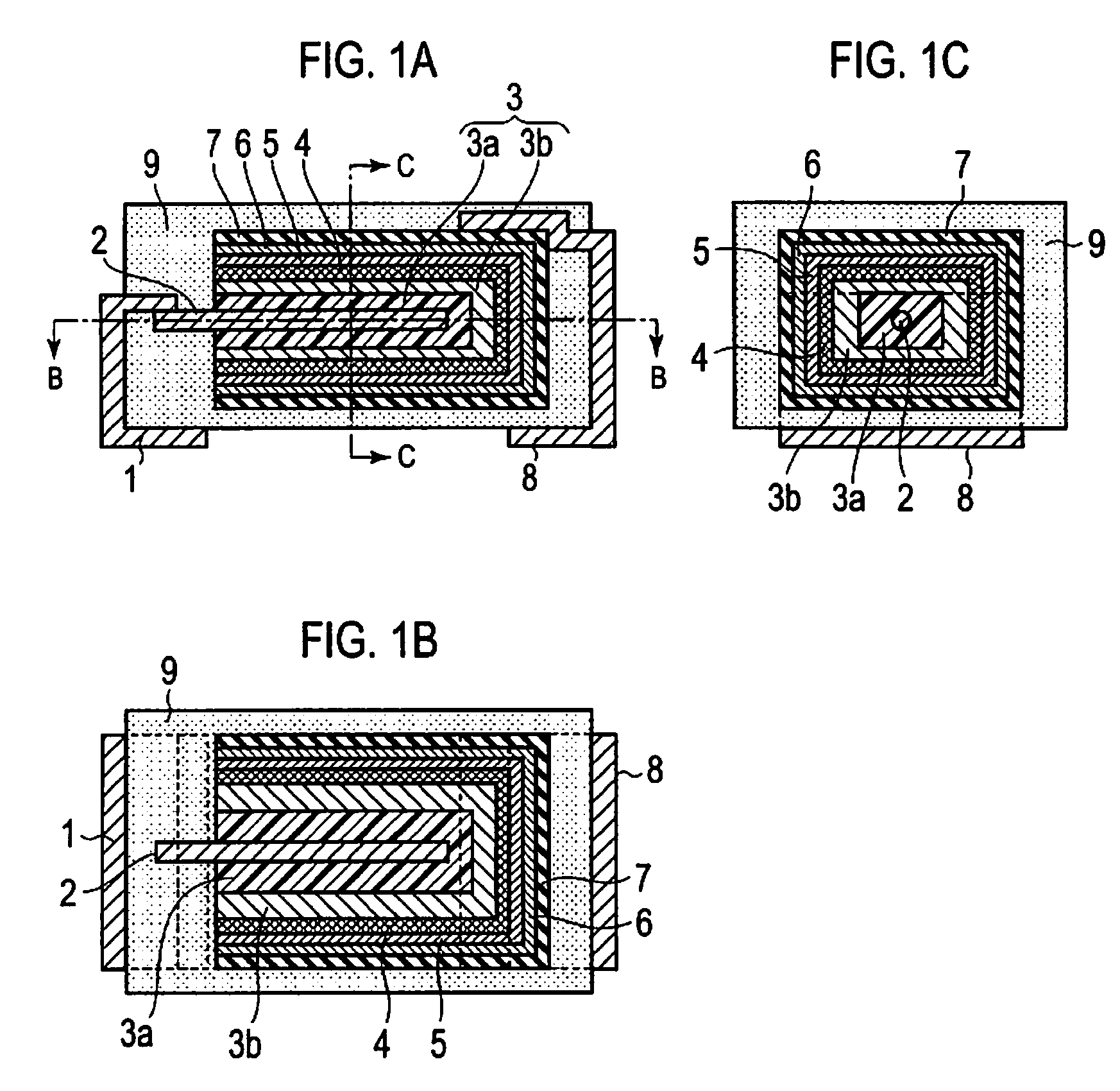
[0036]FIG. 1A is a cross-sectional structural diagram of a solid electrolytic capacitor according to a first embodiment. FIG. 1B is a cross-sectional view of the solid electrolytic capacitor taken along the B-B line of FIG. 1A. FIG. 1C is a cross-sectional view of the solid electrolytic capacitor taken along the C-C line of FIG. 1A. FIG. 6 is a schematic diagram of an enlarged cross-section of an anode body. Descriptions will be provided hereinbelow for the solid electrolytic capacitor according to the first embodiment by use of FIGS. 1 and 6.

[0037]In the solid electrolytic capacitor according to the present embodiment, as shown in FIG. 1, anode lead 2 is made of a valve metal, and is embedded in anode body 3. Anode body 3 includes: first anode portion 3a located around anode lead 2; and second anode portion 3b covering the first anode portion.

[0038]Descriptions will be provided for the internal structure of anode body 3 by use of FIG. 6. First anode portion 3a, which has cuboid sha...

second embodiment

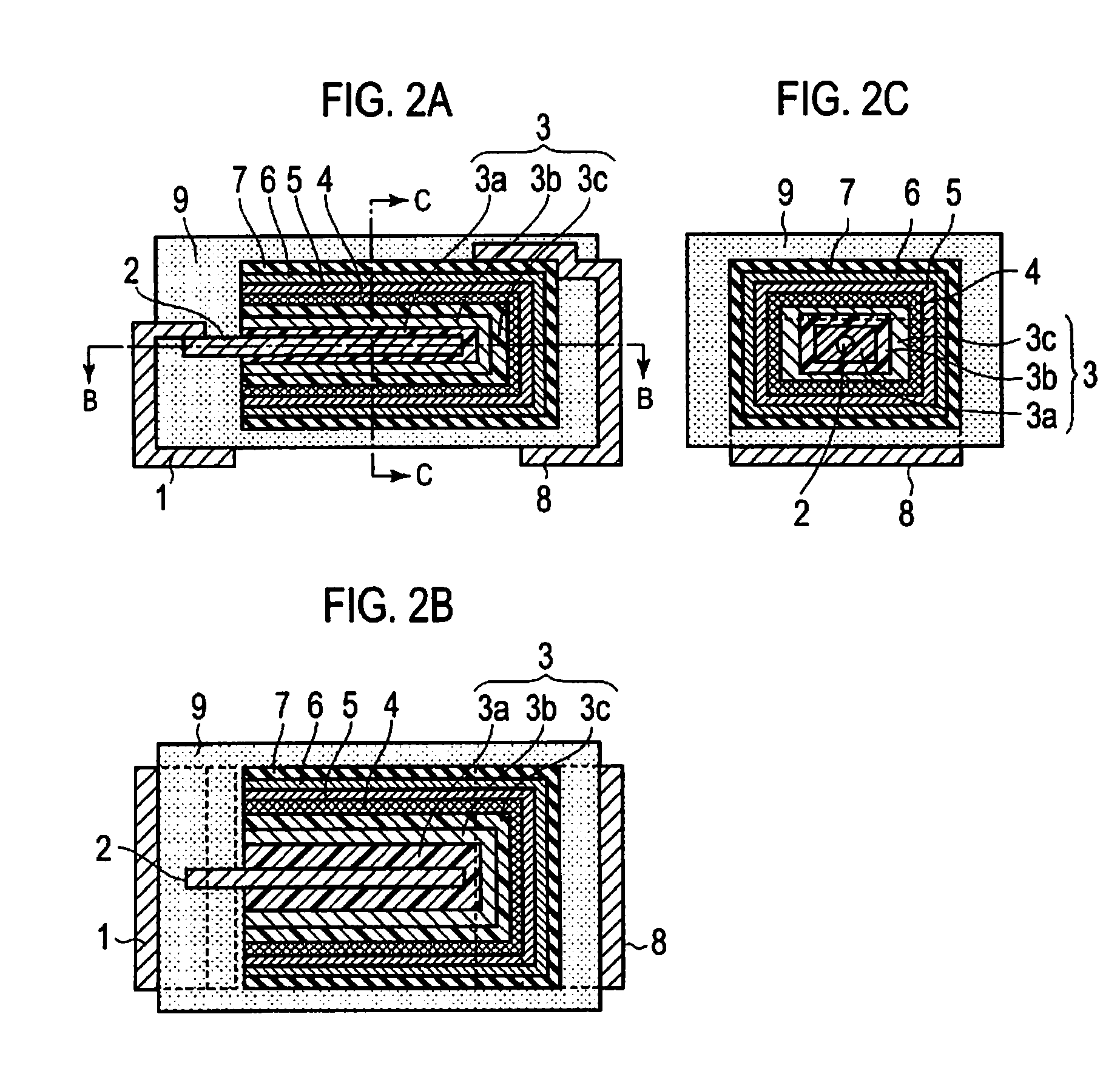
[0056]FIG. 2A is a cross-sectional structural diagram of a solid electrolytic capacitor according to a second embodiment. FIG. 2B is a taken along the B-B line of FIG. 2A. FIG. 2C is taken along the C-C line of FIG. 2A. The configuration of the solid electrolytic capacitor according to the second embodiment is the same as that of the solid electrolytic capacitor according to the first embodiment, except that anode body 3 includes first anode portion 3a, second anode portion 3b and third anode portion 3c as shown in FIGS. 2A, 2B and 2C. Third anode portion 3c may be provided in a way that third anode portion 3c covers at least part of second anode portion 3b.

[0057]The step of forming third anode portion 3c is as follows. Metal particles C, whose particle diameter is smaller than that of metal particles B used for second anode portion 3, are mixed with a binder. Along with the sintered body made of anode lead 2, first anode portion 3a and second anode portion 3b, which is formed in t...

example 2

[0064]Example 2 is the same as example 1 except that the median particle diameter of the metal particles for second anode portion 3b is 0.30 μm.


PUM

PropertyMeasurementUnit
diameteraaaaaaaaaa
diameteraaaaaaaaaa
diameteraaaaaaaaaa

Abstract

The solid electrolytic capacitor includes an anode body formed of a sintered body consisting of metal particles; a dielectric layer provided on the top surface of the anode body; and a conducting polymer layer provided on the top surface of the dielectric layer. The anode body includes a first anode portion and a second anode portion which is provided in a way that the second anode portion covers the first anode portion, and in that the particle diameter of metal particles for the second anode portion is smaller than that of metal particles for the first anode portion.

Description

CROSS REFERENCE TO RELATED APPLICATIONS[0001]This application claims priority based on 35 USC 119 from prior Japanese Patent Application No. P2007-083268 filed on Mar. 28, 2007, the entire contents of which are incorporated herein by reference.BACKGROUND OF THE INVENTION[0002]1. Field of the Invention[0003]The present invention relates to a solid electrolytic capacitor having a smaller equivalent series resistance.[0004]2. Description of Related Art[0005]Solid electrolytic capacitors exhibit good high-frequency characteristics, and have a large capacity although small in size. For this reason, the solid electrolytic capacitors are widely used for power supply circuits of various electronic appliances including personal computers and imaging devices. In addition, the emergence of higher-performance mobile appliances typified by cellular phones and potable music players demands smaller-sized capacitors with a larger capacity.[0006]FIGS. 5A to 5C show cross-sectional structural diagram...

Claims


Application Information

Patent Timeline
Patent Type & Authority Patents(United States)
IPC IPC(8): H01G9/04H01G9/145
CPCH01G9/052H01G9/15Y10T29/417Y10T29/435
Inventor FUJITA, MASAYUKIUMEMOTO, TAKASHINONOUE, HIROSHI
Owner SANYO ELECTRIC CO LTD
Why Eureka
Try Eureka