High speed gasoline unit fuel injector

a fuel injector and high-speed technology, applied in the direction of fuel injection apparatus, fuel feed system, engine components, etc., can solve the problems of limited energy sources, bad performance, emissions, and incomplete fuel carburization

Inactive Publication Date: 2010-07-27
VITESCO TECH USA LLC
View PDF28 Cites 10 Cited by
  • Summary
  • Abstract
  • Description
  • Claims
  • Application Information

AI Technical Summary

Benefits of technology

[0014]One embodiment of the present invention is a fuel injector for forming a metered fuel spray in a fuel injection system of an internal combustion engine. The fuel injector comprises a body having a fuel injector inlet and a fuel injector outlet and having a longitudinal axis extending through the body; a flexible pump diaphragm having a periphery and a central portion, the periphery being secured to the body, the central portion being moveable relative ...

Problems solved by technology

Large fuel particles may not vaporize completely within the combustion cycle, leading to the carburization and incomplete combustion of the fuel, which is inherently bad for performance, and emissions.
This is a limited source of energy for atomization.
That approach leads to manufacturing difficulty and increased risk of obstruction by contamination.
That approach adds to the expense of the entire fuel system, including rails, pump, regulator and lines, which must all be optimized for operation at the higher pressure.
Th...

Method used


Image

  • High speed gasoline unit fuel injector
  • High speed gasoline unit fuel injector
  • High speed gasoline unit fuel injector

Examples


Embodiment Construction

[0042]The fuel injector of the present invention pressurizes fuel to a high pressure for atomization, and atomizes the high pressure fuel as it passes through an outlet valve. The injector yields highly controllable atomization and spray shape. Because the fuel is pressurized in the injector, rail pressure is used only to prevent hot fuel vaporization in the rail, and need not be regulated or damped. Sac volume below the valve seat is eliminated.

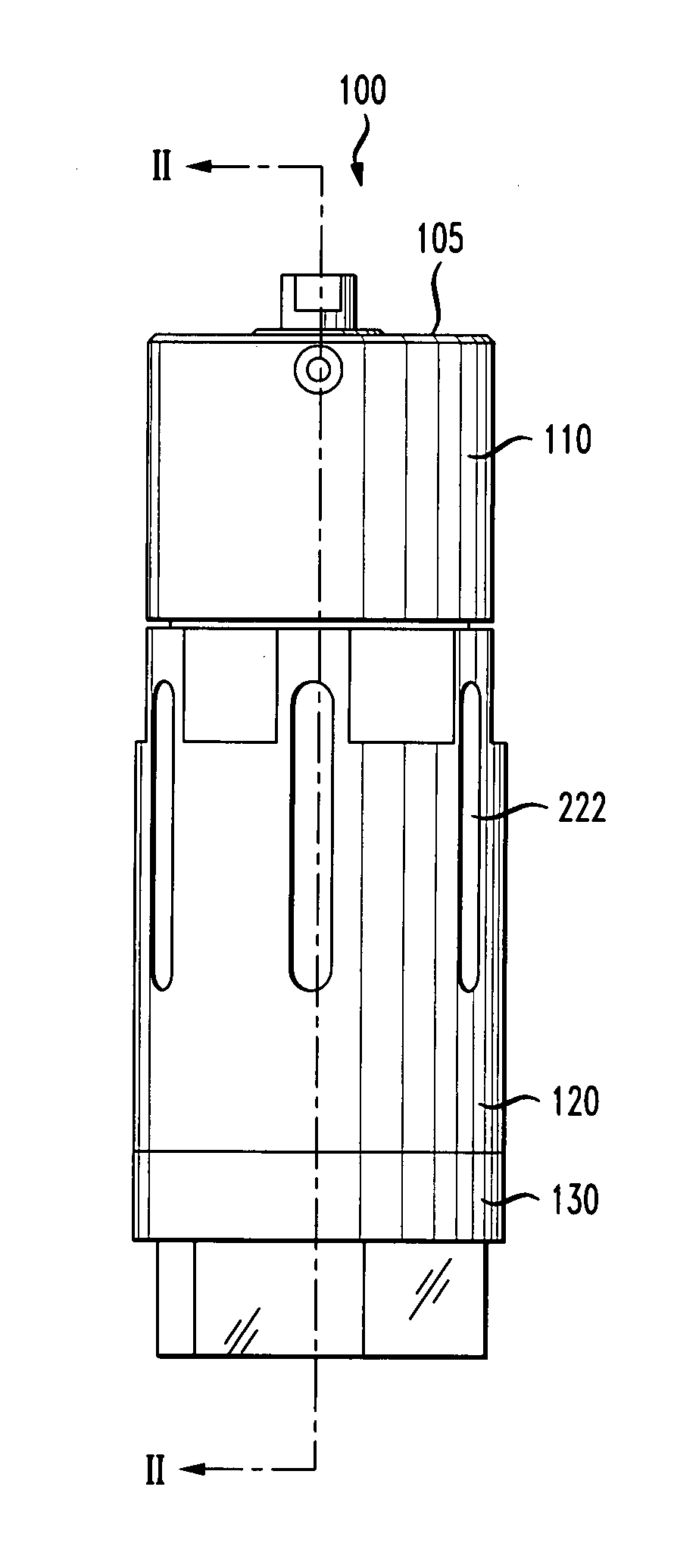
[0043]Referring to FIG. 1, a fuel injector 100 according to the invention includes a fuel injector body 105. The body comprises a pump housing 110, a housing tube 120 and an end cap 130. The body tube may have eddy current reduction slots 222 as shown for reducing magnetic field eddy currents caused by an actuator as described below.

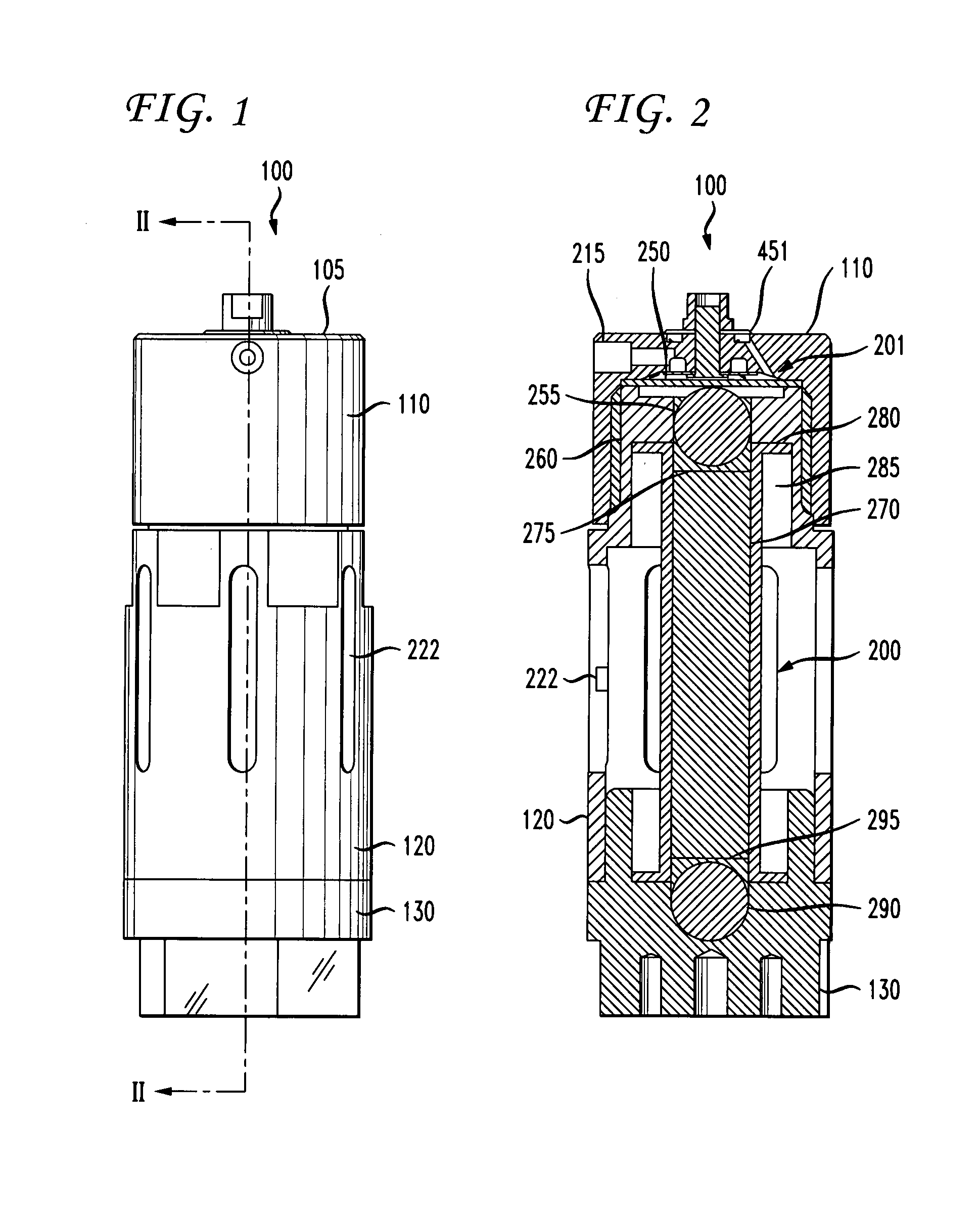
[0044]A sectional view of the fuel injector through section I-II of FIG. 1 is shown in FIG. 2. The injector 100 has a fuel injector inlet 215 and a fuel injector outlet 451. As used herein, the terms “inlet” and ...


PUM


Abstract

A gasoline unit injector includes a high speed, high force actuator such as a magnetrostrictive or piezoelectric actuator. The actuator operates a positive displacement diaphragm pump. The pumping volume is isolated from a supply rail by an inlet check valve, and is isolated from the engine manifold by an outlet check valve. Each of the check valves includes a disk having a central anchor and a peripheral valve seat. Diaphragm movement reduces pump volume and thereby displaces fuel at high pressure through outlet valve. Fuel spray is formed by geometry of outlet valve, the frequency of actuation, and mass and pressure of the displaced fuel. Relaxation of actuator, and therefore diaphragm, increases pump volume and thereby draws fuel into pump volume through the check valve.

Description

CROSS REFERENCE TO RELATED APPLICATIONS[0001]This application claims the benefit of U.S. Provisional Patent Application Ser. No. 60 / 759,158 entitled “High Speed Gasoline Unit Fuel Injector,” filed on Jan. 13, 2006, the contents of which are hereby incorporated by reference herein in their entirety.FIELD OF THE INVENTION[0002]The present invention relates generally to fuel injectors, and more particularly, to a gasoline unit fuel injector having an integral, electronically activated, positive displacement pump.BACKGROUND OF THE INVENTION[0003]Fuel injectors are commonly employed in internal combustion engines to provide precise metering of fuel for introduction into each combustion chamber. Additionally, the fuel injector atomizes the fuel during injection, breaking the fuel into a large number of very small particles, increasing the surface area of the fuel being injected, and allowing the oxidizer, typically ambient air, to more thoroughly mix with the fuel prior to combustion. The...

Claims


Application Information

Patent Timeline
IPC IPC(8): B05B1/08
CPCF02M57/027F02M59/462F02M59/464F02M61/1813B05B1/083B05B17/0607F02M45/02F02M2200/21
Inventor CZIMMEK, PERRY ROBERTSAYAR, HAMID
Owner VITESCO TECH USA LLC
Why Eureka
Try Eureka