Vacuum heat insulation material and cold reserving apparatus with the same

a vacuum heat insulation material and cold reserving technology, applied in the field of vacuum heat insulation materials, can solve the problems of insufficient pinhole resistance, film base easily peeled from each other, and improvement of pinhole resistance, so as to achieve excellent long-term insulation performance, excellent pinhole resistance, excellent gas barrier properties

Active Publication Date: 2010-07-27
PANASONIC CORP
View PDF21 Cites 56 Cited by
  • Summary
  • Abstract
  • Description
  • Claims
  • Application Information

AI Technical Summary

Benefits of technology

[0019]The present invention, which has been devised to solve the aforementioned conventional problems, has an object of providing a high-quality vacuum heat insulation material with excellent long-term insulation performance by providing a laminate film with excellent pinhole resistance and excellent gas barrier properties.
[0020]In order to solve the aforementioned conventional problems, a vacuum heat insulation material of the present invention includes a core material and a covering material which covers the core material and is vacuum sealed, wherein the covering material is a lamination body including two or more plastic film layers, a metal layer, and joining layers for joining therebetween, and the lamination body has a stress-relieving structure in inner layers thereof, the stress-relieving structure being able to prevent penetration and propagation of breakage in a direction perpendicular to the lamination body. When the lamination body is pierced by a foreign body, the propagation of breakage caused by the piercing can be blocked somewhere in the lamination body, thereby preventing the lamination body from having through-pinholes.

Problems solved by technology

However, this resistance is not sufficient to the pinholes that can be caused from the innermost sealant layer side by foreign bodies entered during vacuum packaging.
This results in a through-pinhole even when a foreign body is shorter in length than the thickness of the covering material.
The laminate film composing this conventional impact resistant packaging material, however, has the following problems when used as the covering material of a vacuum heat insulation material.
As a result, in the laminate film including a print ink layer with low peel strength, the wrinkles formed on the print ink layer cause the film bases to be easily peeled from each other.
Therefore, the improvement of the pinhole resistance is not sufficient for the pinholes that can damage the covering material of the vacuum heat insulation material, such as pinholes caused by glass shot, powder dust, and minute foreign bodies including glass fiber.
Therefore, the conventional packaging material, in which insufficient gas barrier properties cause degradation in insulation performance with time, cannot be used as the covering material for vacuum heat insulation materials.

Method used


Image

  • Vacuum heat insulation material and cold reserving apparatus with the same
  • Vacuum heat insulation material and cold reserving apparatus with the same
  • Vacuum heat insulation material and cold reserving apparatus with the same

Examples


first exemplary embodiment

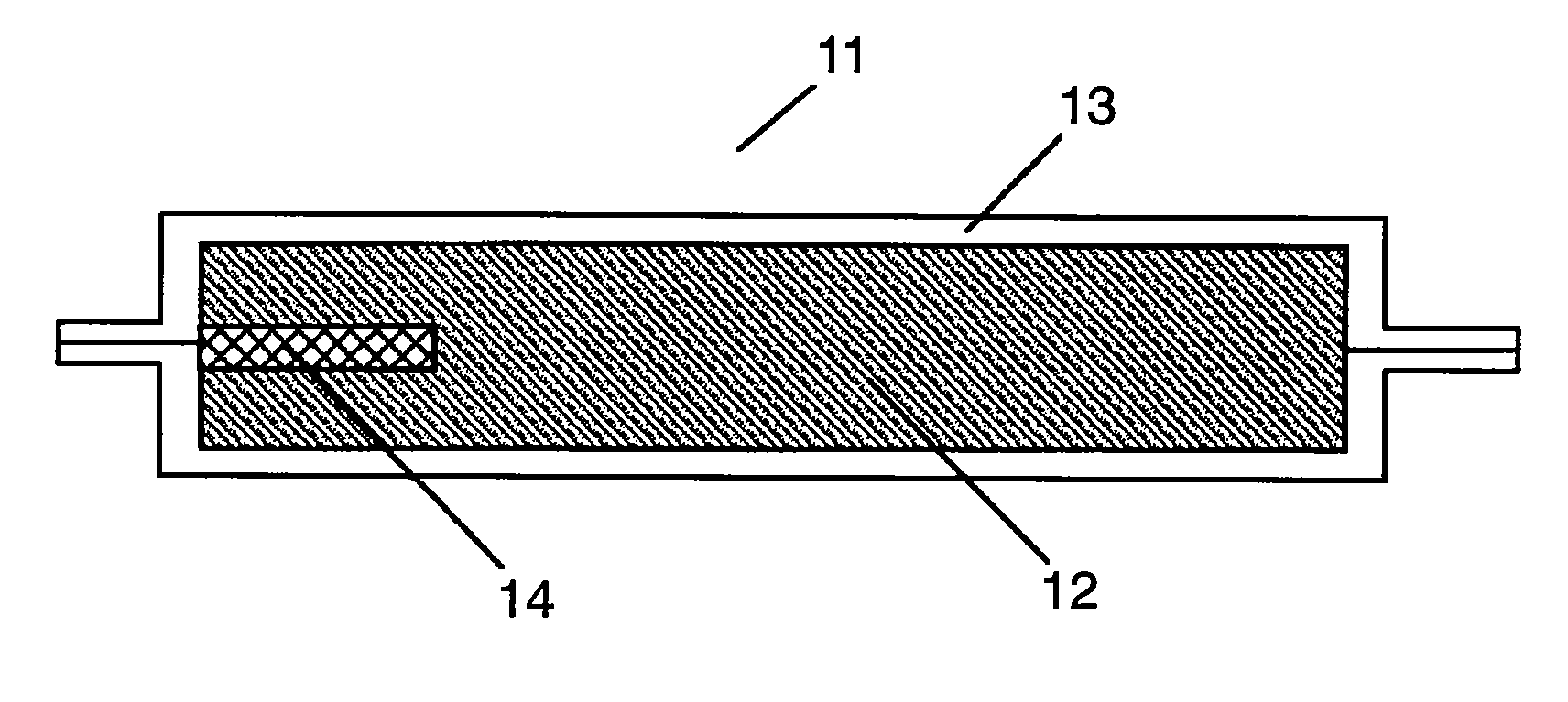
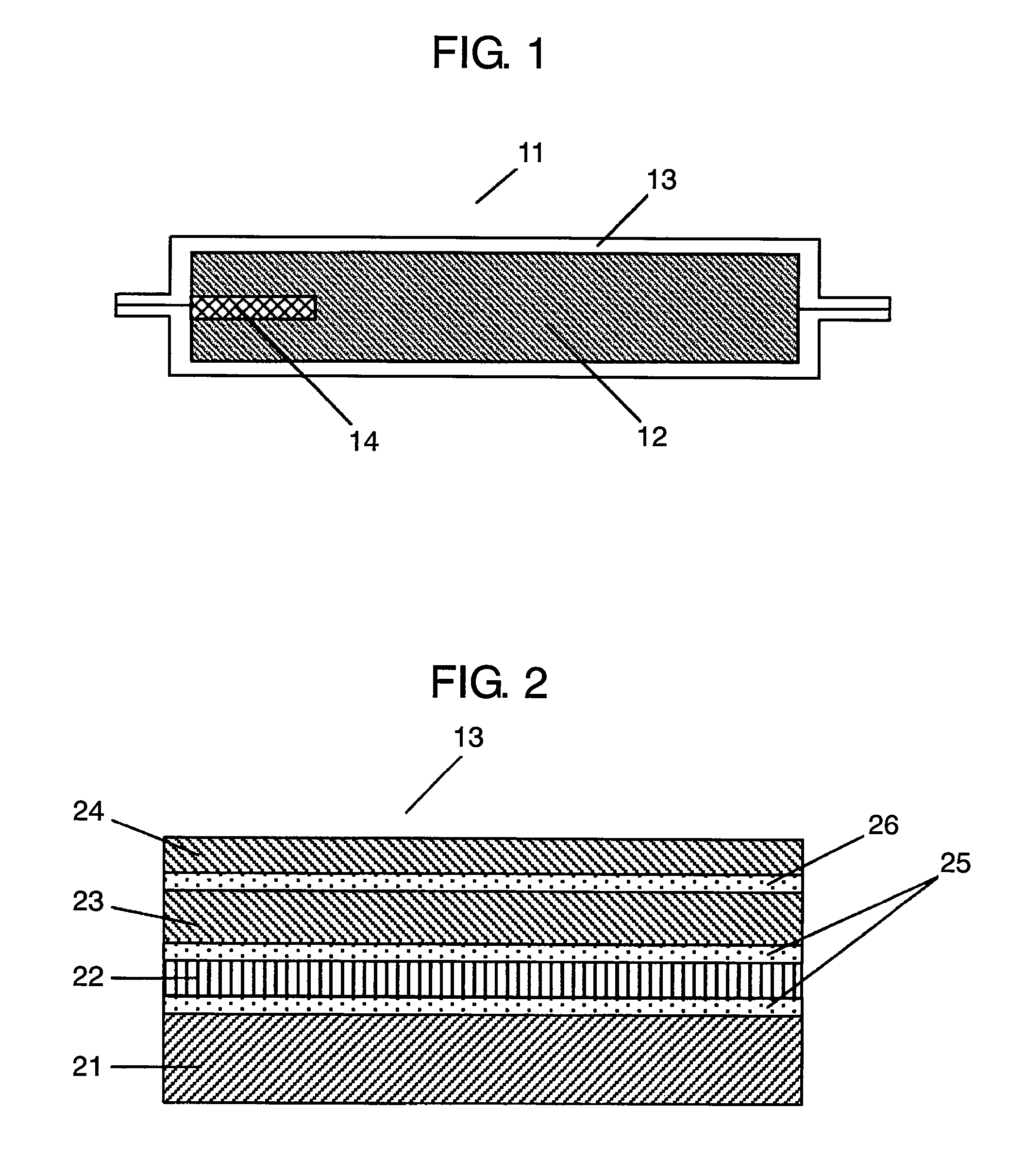
[0087]FIG. 1 is a sectional view of a vacuum heat insulation material of a first embodiment of the present invention. FIG. 2 is a sectional view of a covering material of the vacuum heat insulation material of the first embodiment of the present invention.

[0088]In FIG. 1, vacuum heat insulation material 11 is formed by inserting core material 12 and absorbent 14 into covering material 13 and then vacuuming covering material 13. More specifically, first of all, core material 12 is dried for 30 minutes in a drying furnace at 140° C. Three sides of a laminate film are heat-sealed so as to form covering material 13 into a bag shape. The dried core material 12 and absorbent 14 are inserted to covering material 13 thus formed into the bag shape, and covering material 13 is vacuumed in a vacuum chamber so as to have a pressure of not more than 13 Pa. Then, the opening is heat-sealed.

[0089]Covering material 13 used in the present first embodiment is a lamination body including sealant layer...

second exemplary embodiment

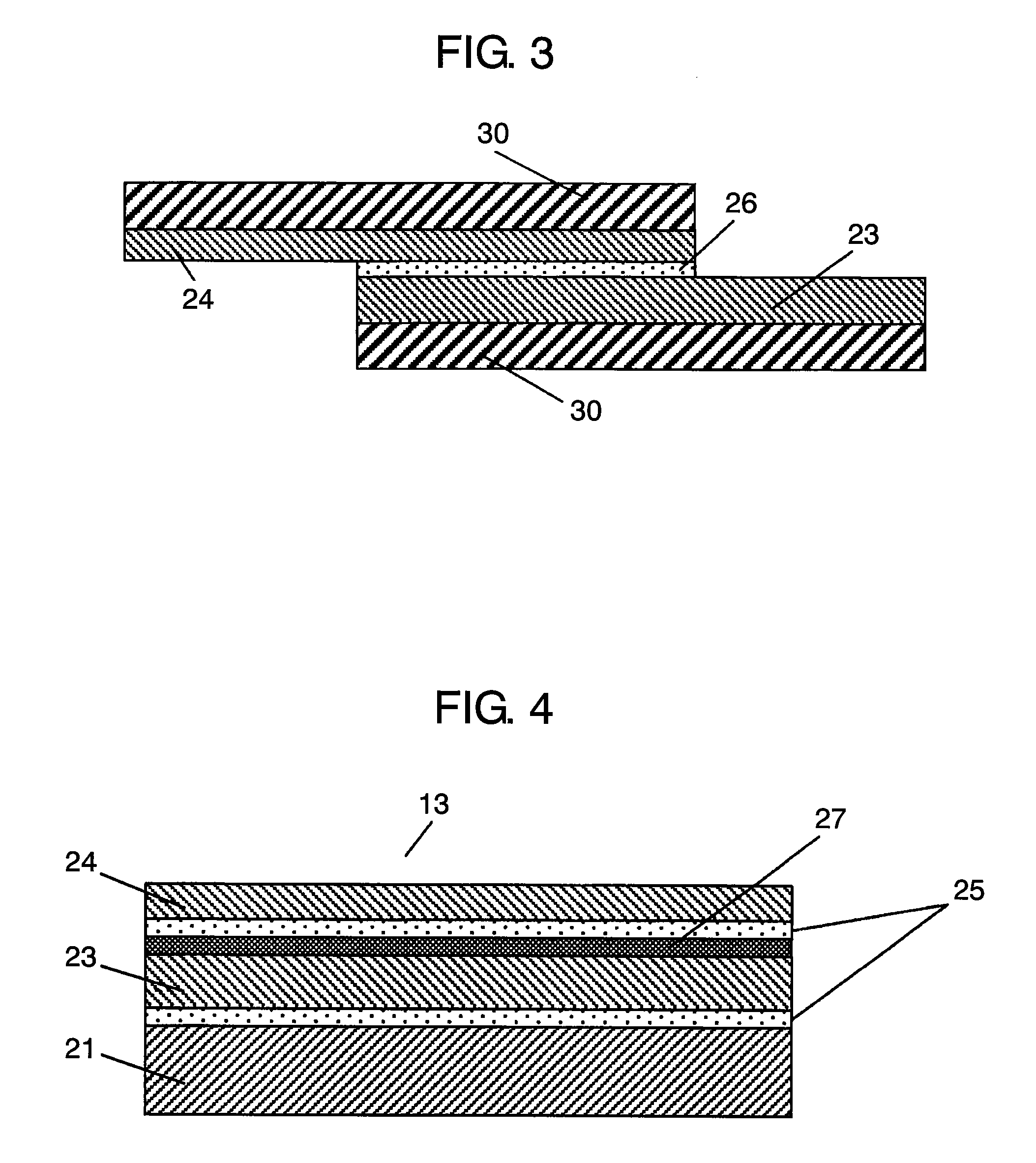
[0114]FIG. 4 is a sectional view of a covering material of a second embodiment of the present invention.

[0115]In FIG. 4, covering material 13 of the present embodiment is a lamination body including sealant layer 21 formed of a 50 μm thick LLDPE film, first plastic film layer 23 formed of a 12 μm thick PET film, and second plastic film layer 24 formed of a 25 μm thick nylon film which are laminated in this order from inside to outside.

[0116]First plastic film layer 23 includes deposited layer 27 on a side opposite to second plastic film layer 24. The deposited film is formed by depositing aluminum as thick as 500 angstroms.

[0117]Sealant layer 21 and first plastic film layer 23 have first adhesive layer 25 disposed therebetween, and first plastic film layer 23 and second plastic film layer 24 also have first adhesive layer 25 disposed therebetween. These layers are dry laminated by a well-known method. As first adhesive layers 25, a well-known urethane adhesive is used.

[0118]The vacu...

third exemplary embodiment

[0129]FIG. 5 is a sectional view of a covering material of a third embodiment.

[0130]In FIG. 5, covering material 13 is a lamination body including sealant layer 21 formed of a 50 μm thick LLDPE film, metal foil layer 22 formed of a 6 μm thick aluminum foil, first plastic film layer 23 formed of a 15 μm thick nylon film, and second plastic film layer 24 formed of a 25 μm thick nylon film which are laminated in this order from inside to outside.

[0131]First plastic film layer 23 and second plastic film layer 24 are formed as coextruded film layers 28 which are laminated by coextrusion.

[0132]Sealant layer 21 and metal foil layer 22 are bonded to each other with first adhesive layer 25 disposed therebetween, and metal foil layer 22 and first plastic film layer 23 are bonded to each other also with first adhesive layer 25 disposed therebetween. First adhesive layers 25 are made of a well-known urethane adhesive.

[0133]The vacuum heat insulation material of the present embodiment is produce...


PUM

PropertyMeasurementUnit
pressureaaaaaaaaaa
shear strengthaaaaaaaaaa
peel strengthaaaaaaaaaa

Abstract

A vacuum heat insulation material has a covering material which is a lamination body including a sealant layer, a metal foil layer, a first plastic film layer, and a second plastic film layer which are laminated in this order from inside to outside via adhesive layers. When a foreign body is pierced into the vacuum heat insulation material, the propagation of breakage caused by the piercing is blocked somewhere inside the lamination body, thereby preventing the formation of through-pinholes. This results in the provision of a high-quality vacuum heat insulation material with excellent long-term insulation performance by using a covering material excellent in gas barrier properties and pinhole resistance to the piercing of minute foreign bodies.

Description

[0001]THIS APPLICATION IS A U.S. NATIONAL PHASE APPLICATION OF PCT INTERNATIONAL APPLICATION PCT / JP2005 / 010159.TECHNICAL FIELD[0002]The present invention relates to a vacuum heat insulation material consisting of a core material and a covering material that covers the core material and is vacuum-sealed.BACKGROUND ART[0003]Energy and environmental issues have become urgent in recent years, and various measures have been suggested to use energy effectively.[0004]As one of the measures, energy saving in household electrical appliances including refrigerators as consumer products is drawing attention. To achieve energy saving in refrigerators, it is necessary to use cold heat effectively and to improve the insulation of the insulating box which forms a refrigerator housing. For this purpose, it is effective that the insulating box is made of an insulation material with high insulation performance. As such high-performance insulation material, vacuum heat insulation materials containing ...

Claims


Application Information

Patent Timeline
Patent Type & Authority Patents(United States)
IPC IPC(8): A47B96/00B32B7/12B32B15/08B32B27/00F16L59/02F16L59/065
CPCB32B7/12B32B15/08B32B27/00F16L59/029F16L59/065B32B15/20B32B27/08B32B27/12B32B27/306B32B27/32B32B27/34B32B27/36B32B27/40B32B3/04B32B2255/10B32B2255/20B32B2255/205B32B2262/101B32B2307/304B32B2307/31B32B2307/558B32B2307/7242B32B2509/10Y10T428/31522Y10T428/31529
Inventor TENRA, TOMOHISAHASHIDA, MASAMICHIHASHIMOTO, KAZUO
Owner PANASONIC CORP
Why Eureka
Try Eureka