Overvoltage protective device and method of overvoltage protection

a protective device and overvoltage protection technology, applied in the direction of overvoltage protection resistors, emergency protective arrangements for limiting excess voltage/current, spark gap details, etc., can solve the problems of voltage drop, the degree of balance between the two conductors may be deteriorated, so as to reduce the size and cost, the effect of easy improvement of symmetry

Inactive Publication Date: 2010-07-27
KIJIMA HITOSHI
View PDF11 Cites 4 Cited by
  • Summary
  • Abstract
  • Description
  • Claims
  • Application Information

AI Technical Summary

Benefits of technology

[0012]When an overvoltage having positive polarity S (t) is applied to an external terminal in the discharge unit E1 side, almost the entire overvoltage thus applied is applied across the discharge units E1 and Ei and across the discharge units En−i+1 and En. Consequently, ones having a lower operating voltage from among the discharge units E1 to Ei and the discharge units En−i+1 to En immediately start to discharge. In this manner, a high rate operation is possible, so overvoltage is not impressed into the apparatus in the indoor side. Thereafter, the other ones from among the discharge units E1 to Ei and the discharge units En−i+1 to En also start to discharge. In this state, overcurrent flows through the clamping type overvoltage protective units V1 and V2. Thereafter, however, the discharge units Ei+1 to En−i start to discharge. By virtue of this discharge, almost the entire overcurrent flows through the discharge units E1 to En, so overcurrent is prevented from flowing through the clamping type overvoltage protective units V1 and V2. Also, in this method, coils and resistors are not used, thus enabling the reduction of size and cost. Further, the discharge units which are first activated are ones having a lower operating voltage from among the discharge units E1 to Ei and the discharge units En−i+1 to En, so it is easy to improve symmetry. The discharge units are arranged in series, so it is also easy to achieve follow current interrupt.
[0013]Thus, according to the configuration of the present invention, problems can simultaneously be solved about reducing the maximum voltage, reducing the size and cost, preventing overcurrent from flowing through a clamping type overvoltage protective component, securing symmetry, enabling follow current interrupt, and the like.

Problems solved by technology

Consequently, the size of the coil 961 becomes large, thus causing a problem in reducing the size and cost.
At the time of normal operation, however, signal current or power supply current flows through the resistor at all times, thus causing a problem of voltage drop.
Further, when there is a deviation of resistance values of resistors inserted to each conductor, the degree of balance between the two conductors may be deteriorated.
Thus it takes longer for the operation to occur.
Also, while voltage is high, the overall current flows through the varistor 901, thus causing a problem of adversely affecting the life of varistor.
Generally, discharge tubes have poor polarity symmetry.
Even combination of several discharge tubes without any varistors, the high response time cannot be achieved like as that of varistors.
When the above overvoltage protective device is used for an electric power system, the resistors 931 and 932 must be replaced with coils, thus causing a problem in reducing the size and cost.

Method used


Image

  • Overvoltage protective device and method of overvoltage protection
  • Overvoltage protective device and method of overvoltage protection
  • Overvoltage protective device and method of overvoltage protection

Examples


first embodiment

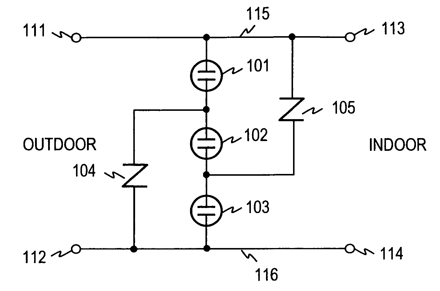
[0049]FIG. 8 shows a configuration of an overvoltage protective device according to First Embodiment of the present invention. In the overvoltage protective device, three discharge units 101, 102 and 103, and two varistors 104 and 105 are used. As shown in FIG. 8, the three discharge units 101, 102 and 103 are connected in series between two conductors 115 and 116. The varistor 104 is connected in parallel to the two discharge units 102 and 103, excluding the discharge unit 101. The varistor 105 is connected in parallel to the two discharge units 101 and 102, excluding the discharge unit 103. Here, the operating voltage of the discharge unit 102 is set lower than a voltage obtained by subtracting the spark-over voltage of the discharge unit 103 from the operating voltage of the varistor 104, and lower than a voltage obtained by subtracting the spark-over voltage of the discharge unit 101 from the operating voltage of the varistor 105, and at the same time higher than the operating v...

second embodiment

[0074]In the present embodiment, there is described a configuration of an overvoltage protective device implementing the method of overvoltage protection described in First Embodiment. FIG. 19 shows a configuration of an overvoltage protective device 200. The overvoltage protective device 200 has four external terminals 201, 202, 203 and 204. The external terminals 201 and 202 are connected to the outdoor side conductors, and the external terminals 203 and 204 are connected to the indoor side (the apparatus side to be protected).

[Variation 1]

[0075]FIG. 20 shows a variation of overvoltage protective device. According to the present variation, the overvoltage protective device 210 has four external terminals 211, 212, 213 and 214. The external terminals 211 and 214 are connected to one conductor 115, and the external terminals 212 and 213 are connected to the other conductor 116.

[Variation 2]

[0076]FIG. 21 shows another variation of overvoltage protective device. According to the prese...


PUM


Abstract

Problems can be solved about reducing the maximum voltage, reducing the size and cost, and so on. According to the invention, three or more discharge units are connected in series between two conductors. Two or more clamping type overvoltage protective units (hereinafter referred to as “clamping units”) are connected in parallel to the discharge units except one or more of the discharge units. The overall operating voltage of the discharge units arranged in parallel to all the clamping units is set lower than any voltage obtained by subtracting from the operating voltage of each clamping unit, the spark-over voltages of the other discharge units connected in parallel to the clamping unit. The overall operating voltage of the discharge units connected in parallel to all the clamping units is set higher than the operating voltage of each discharge unit connected in series to any one of the clamping units.

Description

TECHNICAL FIELD[0001]The present invention relates to an overvoltage protective device and a method of overvoltage protection for protecting apparatuses against overvoltage or overcurrent caused by lightning surge or high-voltage power line.BACKGROUND ART[0002]Both the characteristic of lightning surge, and overvoltage protection technologies have been introduced in the article “Earthing system and lightning protection,” by Hitoshi Kijima, first edition, Corona Co., IEICE, Apr. 5, 2002, pp. 1-54 (Non-Patent literature 1). The technical background required for understanding the present invention will be briefly described below. FIG. 1 shows the profile S (t) of voltage or current caused by lightning surge. Generally, a direct lightning strike causes a current having a peak value of several tens of kA to flow, and an induced lightning surge causes a voltage having a peak value of several kV. Accordingly, values of voltage or current versus time are plotted in FIG. 1. In testing an ove...

Claims


Application Information

Patent Timeline
Patent Type & Authority Patents(United States)
IPC IPC(8): H02H1/00H02H3/22H02H9/06H02H1/04H01C7/12
CPCH01T1/14H02H9/06H01T1/16H02H9/04
Inventor KIJIMA, HITOSHI
Owner KIJIMA HITOSHI
Why Eureka
Try Eureka