Exhaust gas treatment device with insulated housing construction

a technology of exhaust gas treatment device and housing construction, which is applied in the direction of machine/engine, mechanical equipment, separation process, etc., can solve the problems of high manufacturing cost, substantial additional heat, and ineffective reduction of convection heat transfer, and achieve efficient and effective treatment of exhaust gas, compact size, and economical manufacturing

Inactive Publication Date: 2010-08-03
BENTELER AUTOMOTIVE CORP
View PDF21 Cites 6 Cited by
  • Summary
  • Abstract
  • Description
  • Claims
  • Application Information

AI Technical Summary

Benefits of technology

[0009]Yet another aspect of the present invention is to provide an exhaust gas treatment device which has a compact size, efficiently and effectively treats exhaust gas, is thermally insulated, and has an uncomplicated construction which is economical to manufacture. The exhaust gas treatment device has relatively few parts which are constructed to fit together in a unique fashion to provide structural integrity and superior thermal insulation. The exhaust gas treatment device reduces heat loss or thermal transfer to the engine compartment, and is particularly effective in reducing convection heat transfer from the surface of the exhaust gas treatment device. In dual substrate configurations, an annularly-shaped space or air gap is formed between the substrates where the gas sensor is positioned, so as to provide thermal insulation in an area that would normally otherwise be uninsulated. The exhaust gas treatment device is efficient in use, capable of a long operating life, and particularly well adapted for the proposed use.

Problems solved by technology

While maniverters provide a very compact construction, they are relatively expensive to manufacture, and emit substantial additional heat in the engine compartment, and therefore must include some form of heat shield to prevent degradation and / or damage to adjacent components of the vehicle.
While such devices do reduce some radiation heat transfer, they are not very effective in reducing convection heat transfer.
Because the gas sensors associated with exhaust gas treatment devices typically protrude radially outwardly from the components, the associated areas of the housing members are difficult to shield from heat transfer to adjacent vehicle components.

Method used


Image

  • Exhaust gas treatment device with insulated housing construction
  • Exhaust gas treatment device with insulated housing construction
  • Exhaust gas treatment device with insulated housing construction

Examples


Embodiment Construction

[0015]For purposes of description herein, the terms “upper”, “lower”, “right”, “left”, “rear”, “front”, “vertical”, “horizontal” and derivatives thereof shall relate to the invention as oriented in FIGS. 1 and 2. However, it is to be understood that the invention may assume various alternative orientations and step sequences, except where expressly specified to the contrary. It is also to be understood that the specific devices and processes illustrated in the attached drawings, and described in the following specification, are simply exemplary embodiments of the inventive concepts defined in the appended claims. Hence, specific dimensions and other physical characteristics relating to the embodiments disclosed herein are not to be considered as limiting, unless the claims expressly state otherwise.

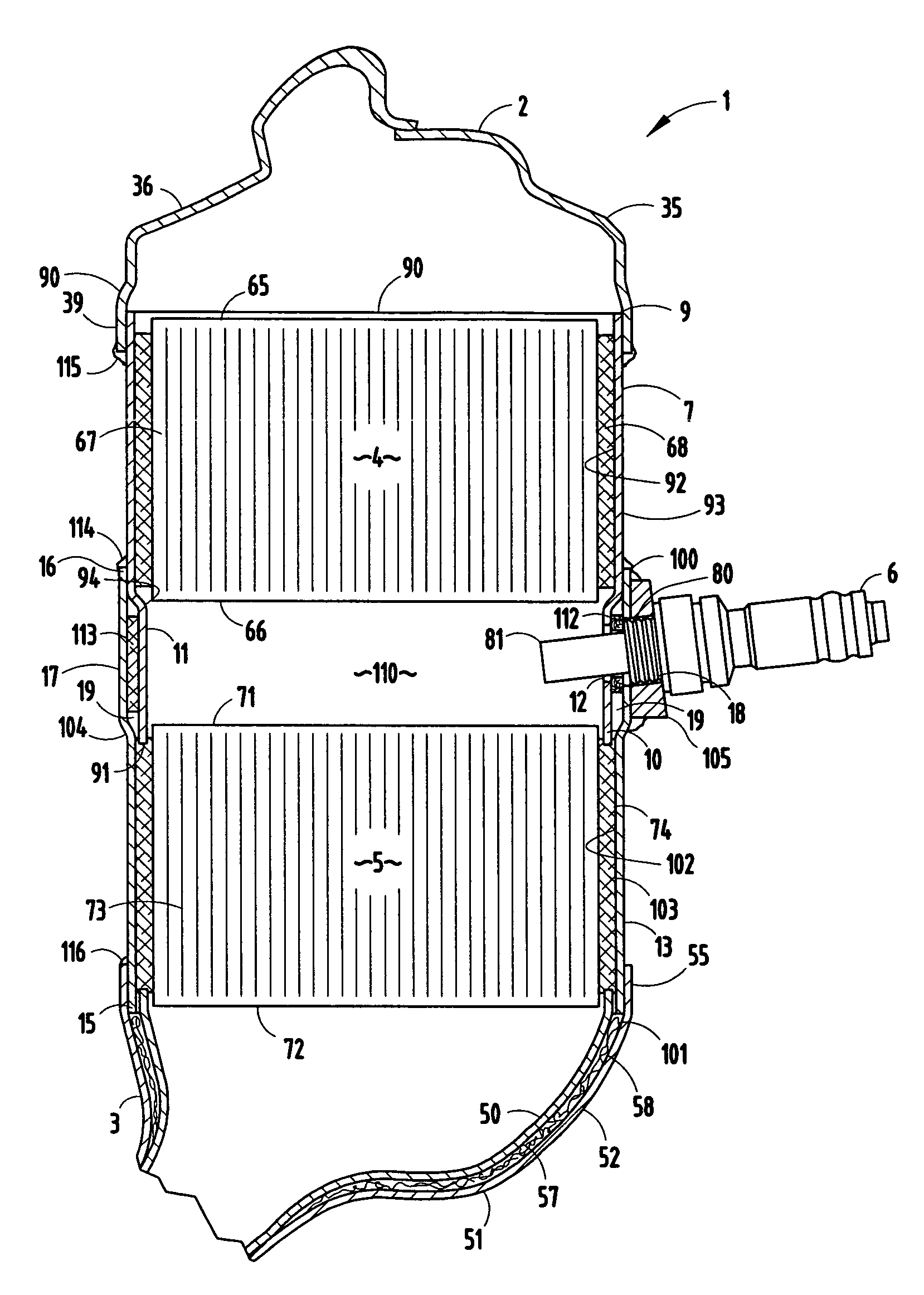
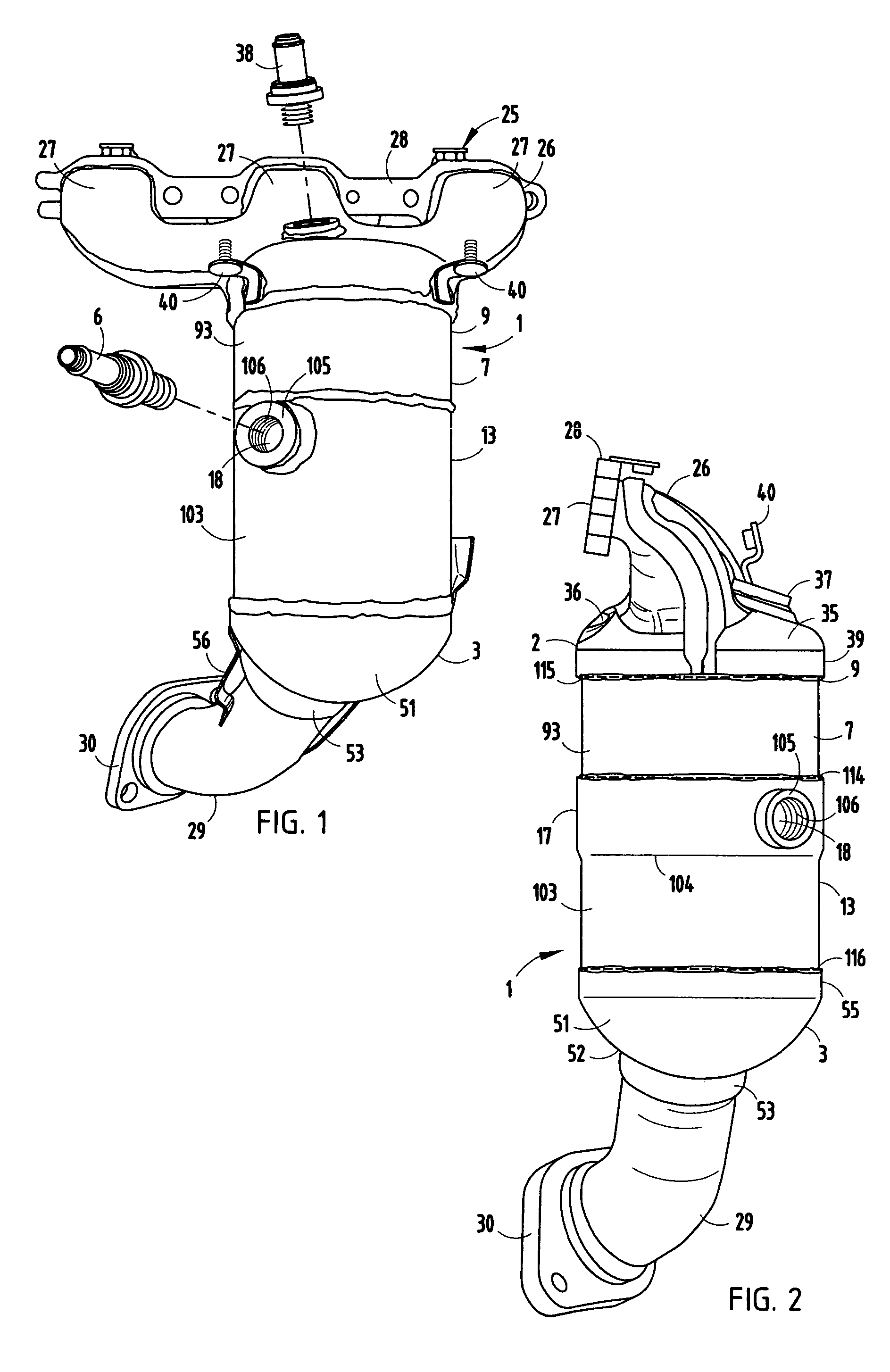
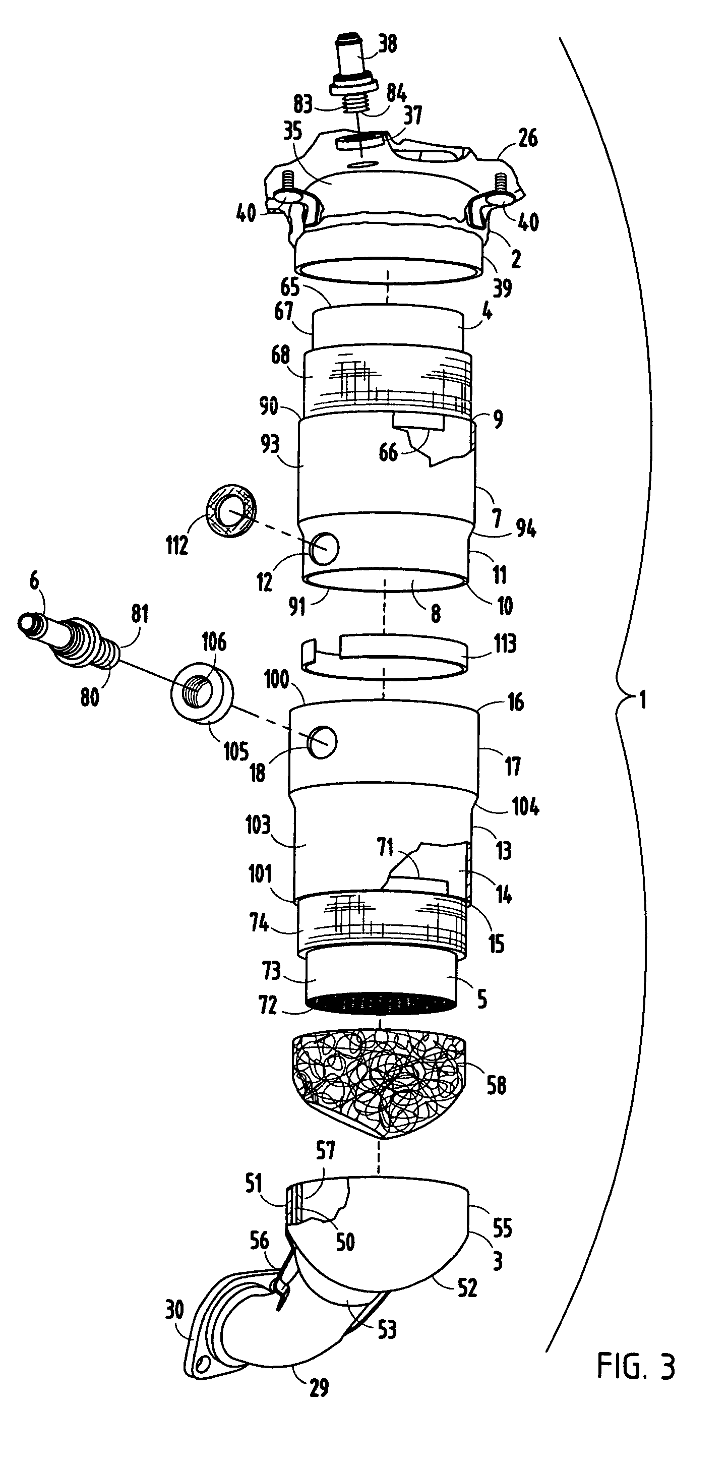
[0016]The reference numeral 1 (FIG. 1) generally designates an exhaust gas treatment device embodying the present invention. As best illustrated in FIG. 3, exhaust gas treatment device 1 ...


PUM

PropertyMeasurementUnit
widthaaaaaaaaaa
surface temperatureaaaaaaaaaa

Abstract

An exhaust gas treatment device for internal combustion engines and the like includes inlet and outlet end caps, two catalyst substrates, and a two-piece housing. A first, cylindrically-shaped housing member has a hollow interior in which one of the substrates is retained, a first end sealingly connected with the inlet end cap, and an opposite second end with a radially reduced section. A second cylindrically-shaped housing member has a hollow interior in which the other one of the substrates is retained, a first end sealingly connected with the outlet end cap, and an opposite second end with a radially enlarged section sized to receive therein the second end of the first housing member, whereby the reduced section of the first housing member and the enlarge section of the second housing member are spaced radially apart a predetermined distance to define an annularly-shaped space or gap which thermally insulates the associated portion of the exhaust gas treatment device.

Description

BACKGROUND OF THE INVENTION[0001]The present invention relates to exhaust gas treatment devices for internal combustion engines and the like, and in particular to an insulated housing construction therefor.[0002]Exhaust gas treatment devices, such as catalytic converters, evaporative emission devices, hydrocarbon scrubbing components and the like, are well known in the art, and are used to treat exhaust gas from internal combustion engines, such as those associated with automobiles, trucks, boats and other vehicles. These exhaust gas treatment devices typically employ catalysts supported by substrates in a housing to catalytically treat the stream of exhaust gas. Due to the high temperature of the exhaust gas, and the normally preferred hot operating temperature of the exhaust gas treatment mechanism, such devices are usually separated or otherwise thermally insulated from adjacent components of the vehicle.[0003]A combination exhaust manifold and catalytic converter, or “maniverter...

Claims


Application Information

Patent Timeline
Patent Type & Authority Patents(United States)
IPC IPC(8): F01N3/10
CPCF01N3/2853F01N13/14F01N13/1894F01N13/0097F01N13/008Y10T29/49927F01N2450/22Y10T29/49968Y10T29/49879Y10T29/49909Y10T29/49345Y10T29/49893Y10T29/49361Y10T29/49398Y10T29/49861Y10T29/49904Y10T29/49915
Inventor HILL, JR., FREDERICK B.SALMONOWICZ, JR., JOSEPH G.SCHNEEMANN, BRAD M.STUDABAKER, JOHN C.
Owner BENTELER AUTOMOTIVE CORP
Why Eureka
Try Eureka