
System and method for making drilling parameter and or formation evaluation measurements during casing drilling

a technology of formation evaluation and measurement method, which is applied in the direction of survey, drilling pipe, borehole/well accessories, etc., can solve the problems of requiring additional time and expense to correct, and wasting time and money

Inactive Publication Date: 2010-08-03
SCHLUMBERGER TECH CORP
View PDF11 Cites 4 Cited by
  • Summary
  • Abstract
  • Description
  • Claims
  • Application Information

AI Technical Summary

Problems solved by technology

The foregoing process is very time consuming and costly.
Additionally, other problems may be encountered when tripping the drill string.
These problems require additional time and expense to correct.
The foregoing techniques require expensive, difficult to operate drill bits that can be retrieved through the casing after the intended wellbore depth is reached in order to provide any form of measurement or directional control, such as using measurement while drilling (“MWD”) and logging while drilling (“LWD”) devices.

Method used


Image

  • System and method for making drilling parameter and or formation evaluation measurements during casing drilling
  • System and method for making drilling parameter and or formation evaluation measurements during casing drilling
  • System and method for making drilling parameter and or formation evaluation measurements during casing drilling

Examples


Embodiment Construction

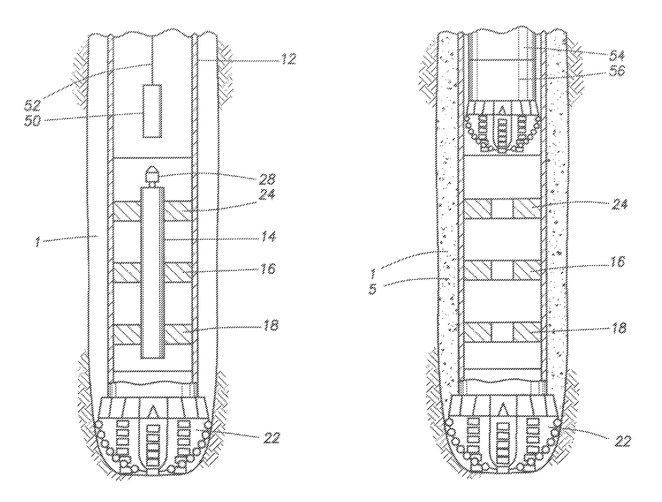
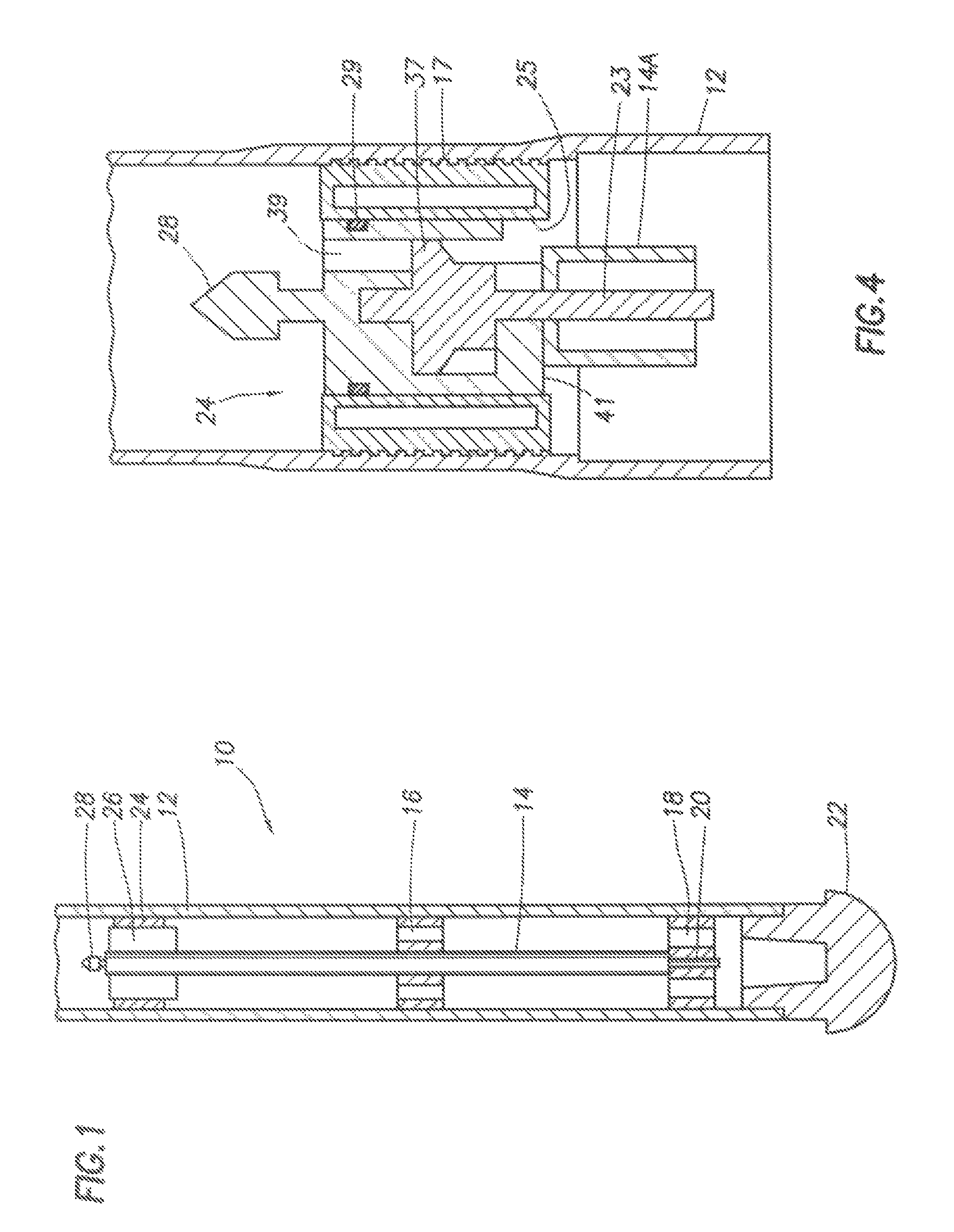
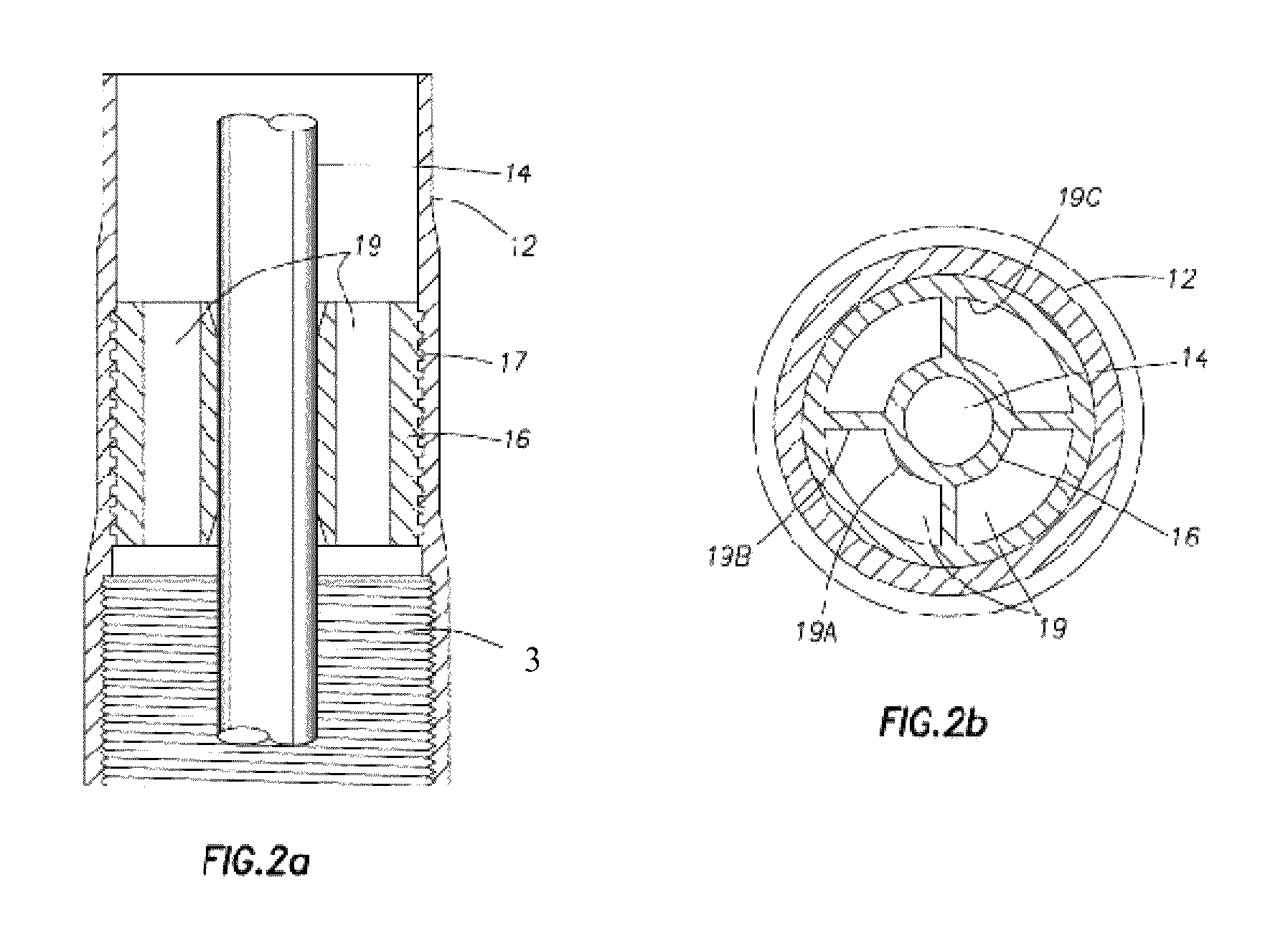
[0024]One example of a casing drilling system including a measurement while drilling (“MWD”) and / or logging while drilling (“LWD”) tool 14 is shown in cross section in FIG. 1. The tool 14 may be disposed inside one or more “joints” (individual segments) of casing 12. The casing 12 may be any type known in the art, and typically has threaded ends (not shown in FIG. 1) to enable threaded coupling of one joint to the next to make up a casing string. The casing 12 may be made from materials ordinarily used for wellbore casing, including carbon steel. In some examples, the casing 12 may be made from non-magnetic alloy such as monel, or an alloy sold under the trademark INCONEL, which is a registered trademark of Huntington Alloys Corporation, Huntington, W. Va. Using non-magnetic material for the casing 12 may enable using magnetic directional sensing devices in the MWD and / or LWD tool 14 (described in more detail below).

[0025]The casing 12 includes a drill bit 22 disposed at the lower e...


PUM


Abstract

A casing drilling system includes a casing having a drill bit at one end. The drill bit is capable of drilling subsurface formations and formed from a material removable by drilling or chemical exposure. The chemical is substantially harmless to the casing. The system includes a centralizer affixed to an interior of the casing. The centralizer includes a receptacle therein for engaging a measurement while drilling tool. The centralizer is formed from a material removable by drilling or chemical exposure, wherein the chemical is substantially harmless to the casing. The system includes a measurement while drilling tool configured to move along the interior of the casing and to engage with the centralizer. The tool includes a device to measure a drilling parameter or a formation parameter. The tool including a latch at an upper end thereof for engagement with a retrieval tool moved through the interior of the casing.

Description

BACKGROUND OF THE INVENTION[0001]1. Field of the Invention[0002]The invention relates generally to the field of apparatus and methods for measuring drilling parameters and / or formation parameters during wellbore drilling. More particularly, the invention relates to structures and techniques for making such measurements in drilling operations known as “casing drilling.”[0003]2. Background Art[0004]Wellbores are drilled into the Earth's subsurface to recover hydrocarbons and other desirable materials trapped in geological formations in the subsurface. A wellbore is typically drilled by advancing a drill bit through the subsurface formations. The drill bit is attached to the lower end of a “drill string” suspended from a drilling rig. The drill string is a long string of sections of drill pipe that are connected together end-to-end to form a long shaft for driving the drill bit further into the subsurface. A bottom hole assembly (“BHA”) containing various instrumentation and / or devices...

Claims


Application Information

Patent Timeline
Patent Type & Authority Patents(United States)
IPC IPC(8): E21B10/64
CPCE21B17/1007E21B17/1042E21B17/20E21B47/00E21B7/20E21B47/12E21B47/18
Inventor CLARK, BRIAN
Owner SCHLUMBERGER TECH CORP
Learn More