Radio-frequency power amplifier

a power amplifier and radio frequency technology, applied in the direction of amplifiers, amplifiers with semiconductor devices only, amplifiers with semiconductor devices, etc., can solve the problems of reducing affecting the miniaturization and cost reduction of mobile phones, and the difficulty of maintaining a constant temperature in the mobile phone, etc., to achieve the effect of sufficient temperature compensation

Active Publication Date: 2010-08-03
GK BRIDGE 1
View PDF7 Cites 61 Cited by
  • Summary
  • Abstract
  • Description
  • Claims
  • Application Information

AI Technical Summary

Benefits of technology

[0022]Therefore, to solve the above problem, an object of the present invention is to provide a radio-frequency power amplifier having a bias circuit capable of making the temperature dependence, of the idle current of an amplifying transistor, lower than is conventionally the case and thus sufficiently compensating for temperature.
[0025]Based on the configuration described above, the bias circuit includes the plurality of temperature compensation circuits. This makes it possible to make the temperature dependence, of the idle current of the first transistor, lower than is conventionally the case. As a result, based on the present embodiment, it is possible to provide a radio-frequency power amplifier having a bias circuit capable of sufficiently compensating for temperature.
[0034]Based on the present invention, it is possible to provide a radio-frequency power amplifier having a bias circuit capable of making the temperature dependence, of the idle current of an amplifying transistor, lower than is conventionally the case and thus sufficiently compensating for temperature.

Problems solved by technology

However, some of the components may produce heat, and the higher the degree of integration of each component is made by miniaturizing the components, the more difficult it becomes to maintain a constant temperature in the mobile phone.
However, this requires separately a negative voltage generator so as to control the gate voltage, and therefore hinders the miniaturization and the cost reduction of the mobile phone.
As a result, the base potential of the emitter-follower transistor Tr2 may become so unstable that it is impossible to supply a stable bias current.
However, in such a system as GSM (Global System for Mobile Communications) that uses a large transmitted signal, it is necessary to use the capacitor C1 that has a considerably large capacitance, which significantly increases the size of the capacitor C1.
On the other hand, in view of the miniaturization of the mobile phone, there are limitations to increasing the size of the capacitor C1.
Therefore, with the configuration of FIG. 8, it is difficult to supply a stable bias current.
However, with the radio-frequency power amplifier of FIG. 9, it is impossible to sufficiently suppress the temperature dependence of the idle current of the amplifying transistor Tr1, due to the circuit configuration of the temperature compensation circuit 11, and therefore it is impossible to sufficiently compensate for temperature.
As a result, the power gain falls, which hinders high efficiency.
Consequently, with the radio-frequency power amplifier of FIG. 9, there are limitations to increasing the resistance value of the resistance element R2, and therefore it is difficult to sufficiently compensate for temperature.

Method used


Image

  • Radio-frequency power amplifier
  • Radio-frequency power amplifier
  • Radio-frequency power amplifier

Examples


first embodiment

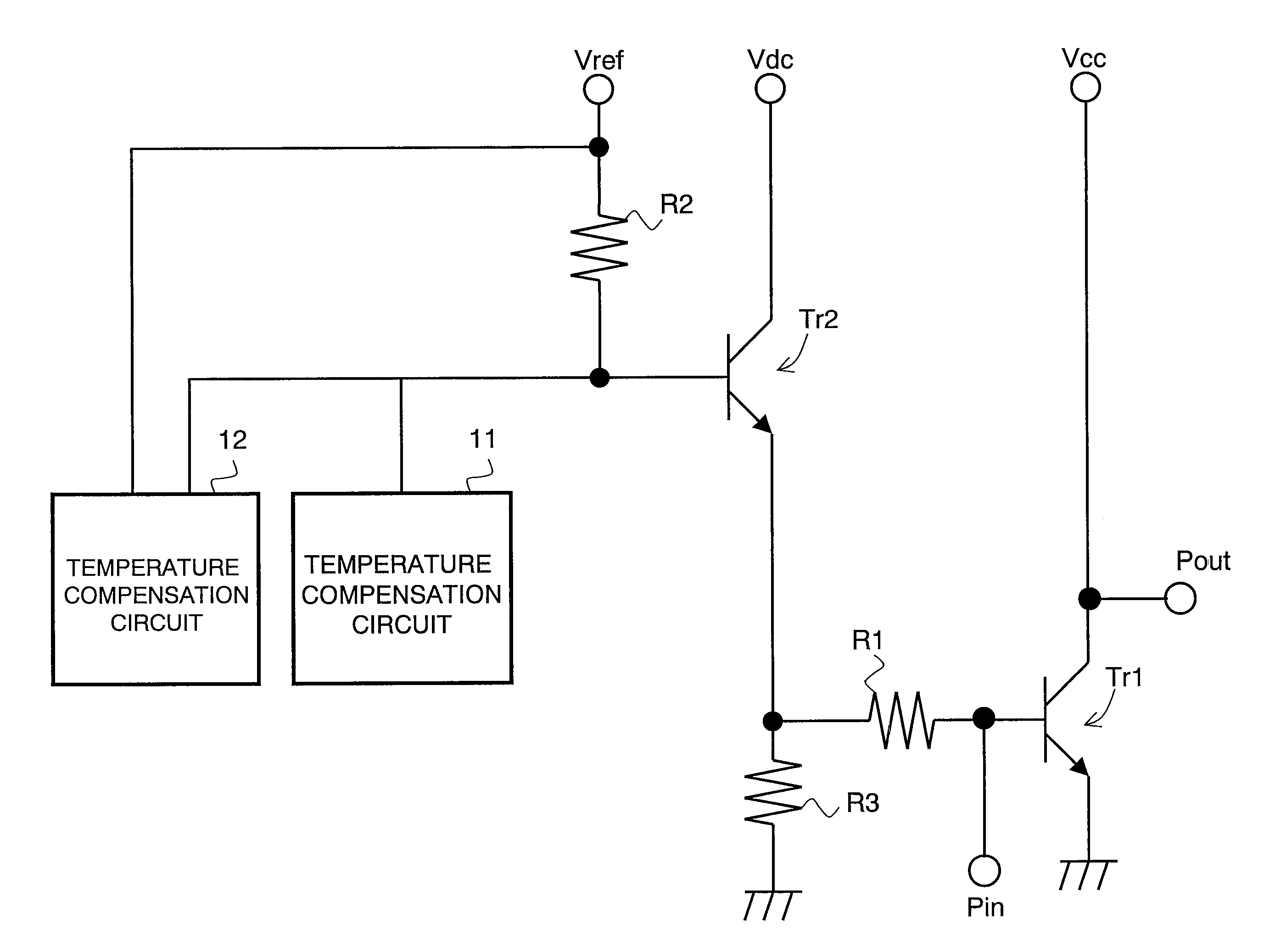
[0047]With reference to FIG. 1, the circuit configuration of a radio-frequency power amplifier according to a first embodiment of the present invention will be described. FIG. 1 is a diagram showing the circuit configuration of the radio-frequency power amplifier according to the first embodiment. The radio-frequency power amplifier of FIG. 1 includes an amplifying transistor Tr1 and a bias circuit. Note that, in FIG. 1, the same components as those of FIG. 9 will be denoted by the same numerals and therefore will not be described in detail.

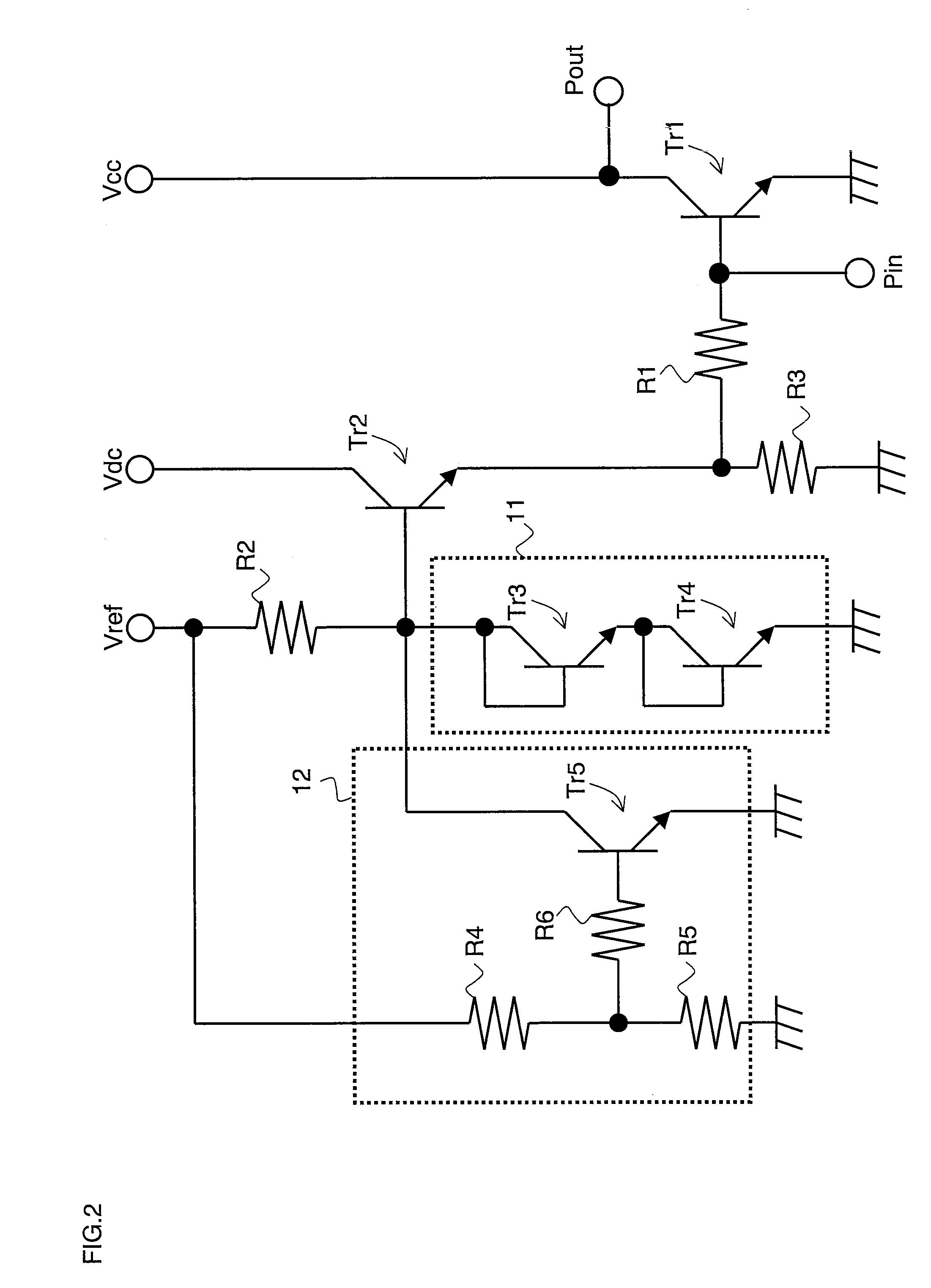
[0048]The bias circuit, which supplies a bias current to the base terminal of the amplifying transistor Tr1, includes an emitter-follower transistor Tr2, resistance elements R1, R2 and R3, a temperature compensation circuit 11, and a temperature compensation circuit 12.

[0049]The temperature compensation circuit 11, which is connected to the base terminal of the emitter-follower transistor Tr2, compensates for the idle current of the amplifying tr...

second embodiment

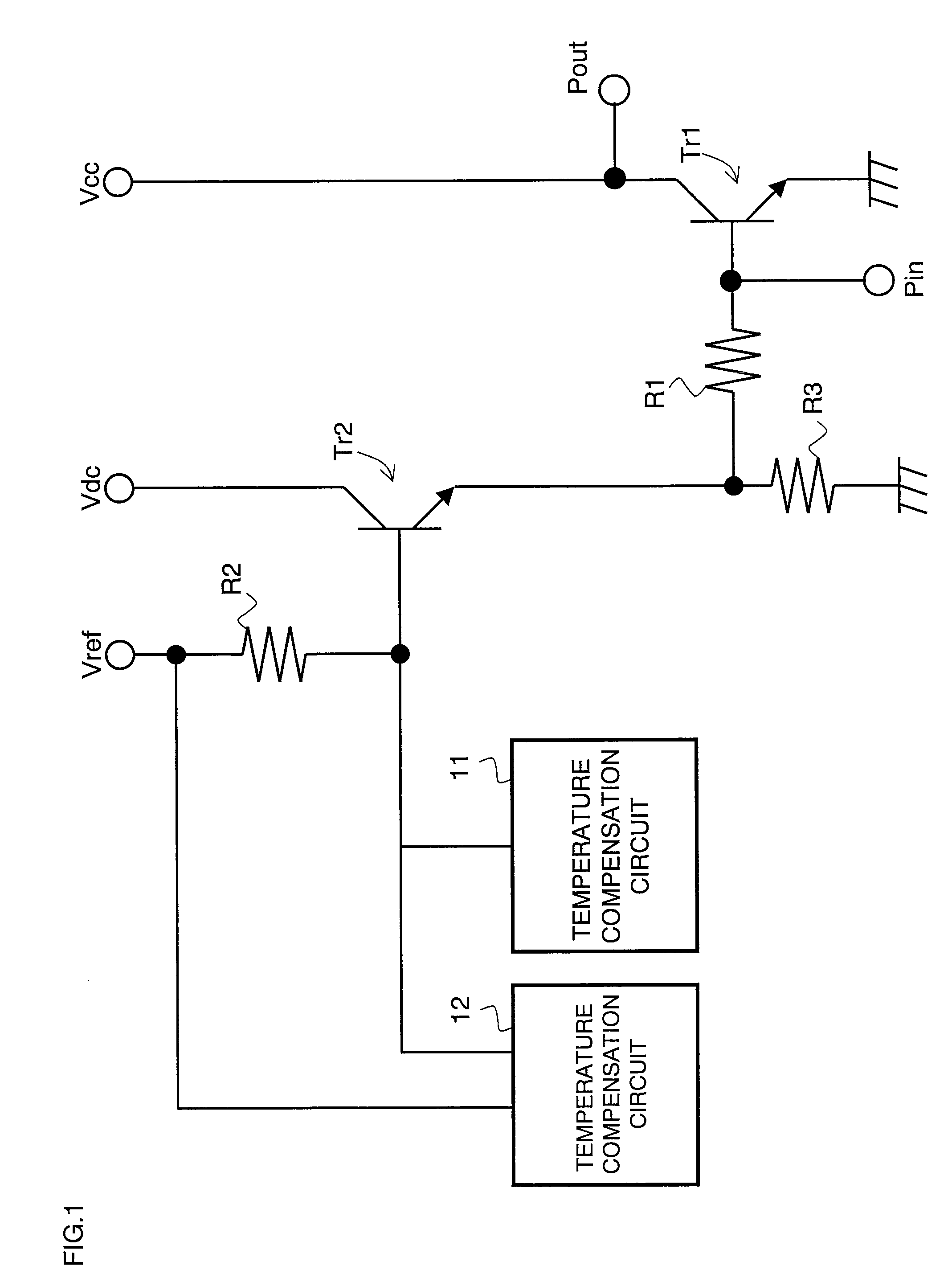
[0061]With reference to FIG. 5, the circuit configuration of a radio-frequency power amplifier according to a second embodiment of the present invention will be described. FIG. 5 is a diagram showing the circuit configuration of the radio-frequency power amplifier according to the second embodiment. The radio-frequency power amplifier of FIG. 5 is different from the radio-frequency power amplifier of FIG. 2 in that the radio-frequency power amplifier of FIG. 5 further includes a mode switching circuit 13. The other components of the circuit configuration of FIG. 5 are the same as those of the circuit configuration of FIG. 2, and therefore will be denoted by the same numerals and will not be described.

[0062]The mode switching circuit 13 includes a power supply circuit 131, a resistance element R7, a resistance element R8, and a transistor Tr6. The base terminal of the transistor Tr6 is connected to the output of the power supply circuit 131 via the resistance element R7. The collecto...

third embodiment

[0066]With reference to FIG. 6, the circuit configuration of a radio-frequency power amplifier according to a third embodiment of the present invention will be described. FIG. 6 is a diagram showing the circuit configuration of the radio-frequency power amplifier according to the third embodiment. The radio-frequency power amplifier of FIG. 6 is different from the radio-frequency power amplifier of FIG. 2 in that the radio-frequency power amplifier of FIG. 6 further includes a temperature compensation circuit 14. The other components of the circuit configuration of FIG. 6 are the same as those of the circuit configuration of FIG. 2, and therefore will be denoted by the same numerals and will not be described.

[0067]The temperature compensation circuit 14, which is similar in configuration to the temperature compensation circuit 12, is connected to the base terminal of the emitter-follower transistor Tr2 and thus the temperature compensation circuit 14, as well as the temperature comp...


PUM


Abstract

A bias circuit operable to supply a bias current to a first transistor includes: a second transistor having a collector terminal connected to a first power supply; a first resistance element having one end connected to an emitter terminal of the second transistor and having the other end connected to a base terminal of the first transistor; a second resistance element having one end connected to the emitter terminal of the second transistor and having the other end connected to ground potential; at least one third resistance element provided between a base terminal of the second transistor and a second power supply; and a plurality of temperature compensation circuits connected to the base terminal of the second transistor which are operable to control a base potential of the second transistor so that the potential falls as a temperature rises.

Description

BACKGROUND OF THE INVENTION[0001]1. Field of the Invention[0002]The present invention relates to a radio-frequency power amplifier, and particularly to a radio-frequency power amplifier of which a bias circuit for supplying a bias current to the amplifying transistor includes a plurality of temperature compensation circuits.[0003]2. Description of the Background Art[0004]In recent years, due to the installation of various application functions in a mobile communication device such as a mobile phone, the number of components of the mobile phone tends to increase in accordance with the number of necessary components to control these functions. On the other hand, the mobile phone is miniaturized, and accordingly, it is necessary to miniaturize the components so as to increase the degree of integration of each component. However, some of the components may produce heat, and the higher the degree of integration of each component is made by miniaturizing the components, the more difficult...

Claims


Application Information

Patent Timeline
Patent Type & Authority Patents(United States)
IPC IPC(8): H03F3/04
CPCH03F1/0261H03F1/302H03F3/19H03F3/245H03F2200/18H03F2200/27H03F2200/447
Inventor MATSUDA, SHINGOMAKIHARA, HIROKAZUTATEOKA, KAZUKIINAMORI, MASAHIKO
Owner GK BRIDGE 1
Why Eureka
Try Eureka