Optical fiber laser

a technology fiber optics, applied in the field of optical fiber lasers, can solve the problems of high cost large number of semiconductor excitation lasers cannot be expected, limited number of semiconductor excitation lasers to be bundled, etc., and achieve the effect of high reliability and enabled high-power operation

Inactive Publication Date: 2010-08-03
HITACHI CABLE
View PDF6 Cites 3 Cited by
  • Summary
  • Abstract
  • Description
  • Claims
  • Application Information

AI Technical Summary

Benefits of technology

[0011]In the V-groove method shown in FIG. 5B, a complex process is required for forming a cuneal-shaped V-groove at the side face of the optical fiber and this process reduces the mechanical strength of the optical fiber extremely.
[0013]An object of the present invention is to provide a low-cost, high reliability and high-powered operation enabled optical fiber laser in order to solve the above problems.
[0024]According to the present invention, a low-cost, high reliability and high-powered operation enabled optical fiber laser can be realized.

Problems solved by technology

Therefore, in order to attain high power, there occurs a problem to be solved for searching how to introduce the high power excitation light into the narrow end face of the inner clad.
Even in the method in which the semiconductor laser light provided in single-emission is coupled to the multi-mode optical fiber at first, and then this coupled laser light is bundled and focused so as to be introduced to the end face of the inner clad region, the number of semiconductor excitation lasers to be bundled is limited and hence the large number of semiconductor excitation lasers can not be expected.
As it is required to make the output of the individual semiconductor excitation laser large enough to provide a high power, it may result in the shorter lifetime and high costs of semiconductor excitation lasers.
In attempting to oscillate the laser in a high power, the power density at the light propagation regions becomes very large.
The power density of the excitation light is very high near the introduction end part of the excitation light, and there may be such a risk that the optical fiber is damaged.
Though the end-face excitation method provides a high conversion efficiency for the laser oscillation light, the overall power of the excitation light to be introduced is limited.
In addition, a single-mode failure in the semiconductor excitation laser may affect the power fluctuation for the overall optical fiber laser.
In the V-groove method shown in FIG. 5B, a complex process is required for forming a cuneal-shaped V-groove at the side face of the optical fiber and this process reduces the mechanical strength of the optical fiber extremely.
However, this method requires the process in which individual multi-mode optical fiber for introducing the semiconductor laser light is fusion spliced one-by-one onto the side face of the double-clad type optical fiber, this fusion splicing includes many pieces of precise works and the structure of fusion splicing points becomes complex.
The semiconductor laser to be used has a single emission structure which is easily coupled to the multi-mode optical fiber, and such a low-cost and overall high optical powered semiconductor laser as having a bar and stuck structure is not suitable for this excitation method.

Method used


Image

  • Optical fiber laser
  • Optical fiber laser
  • Optical fiber laser

Examples


Embodiment Construction

[0036]Now, referring to the attached drawings, one embodiment of the present invention will be described in detail.

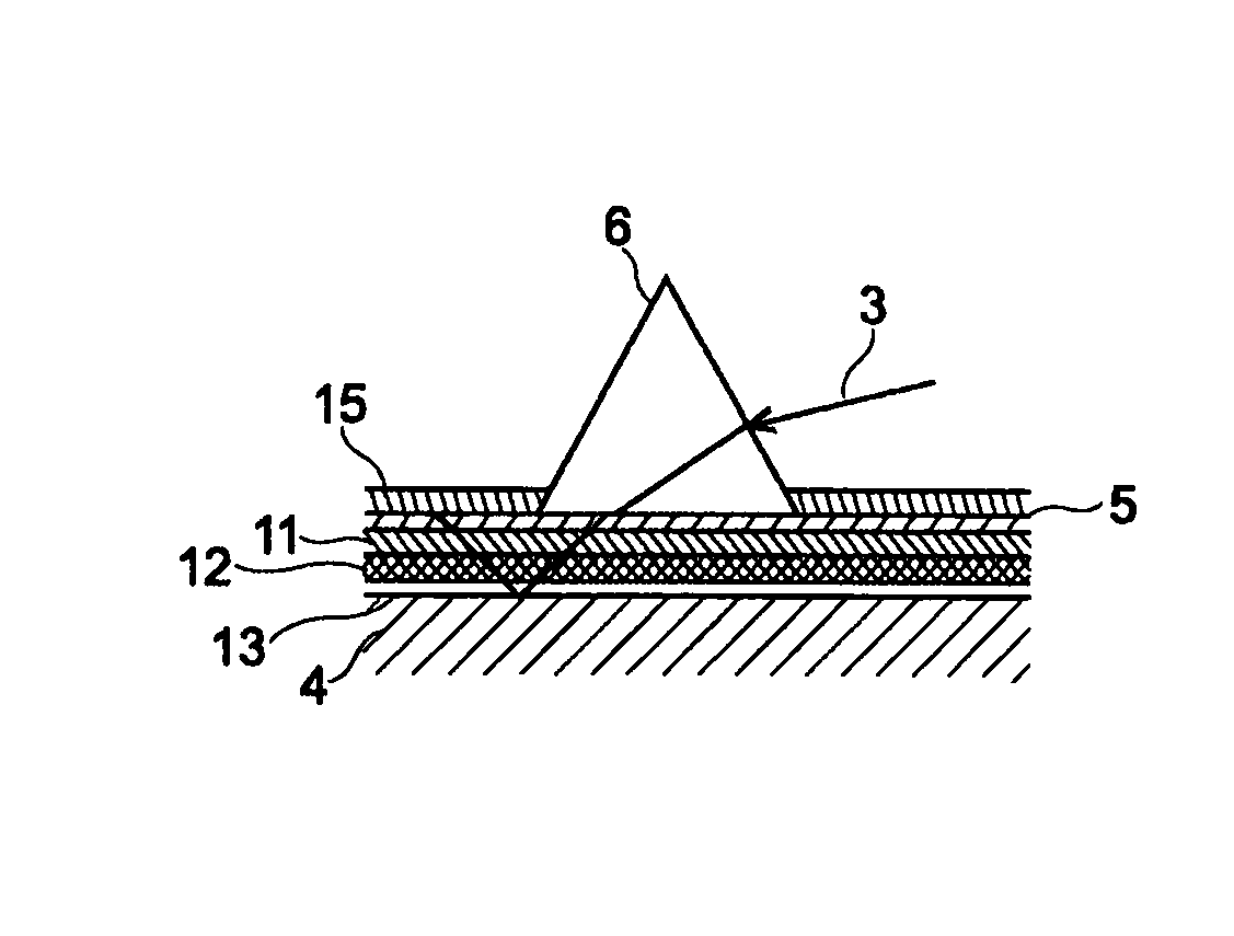
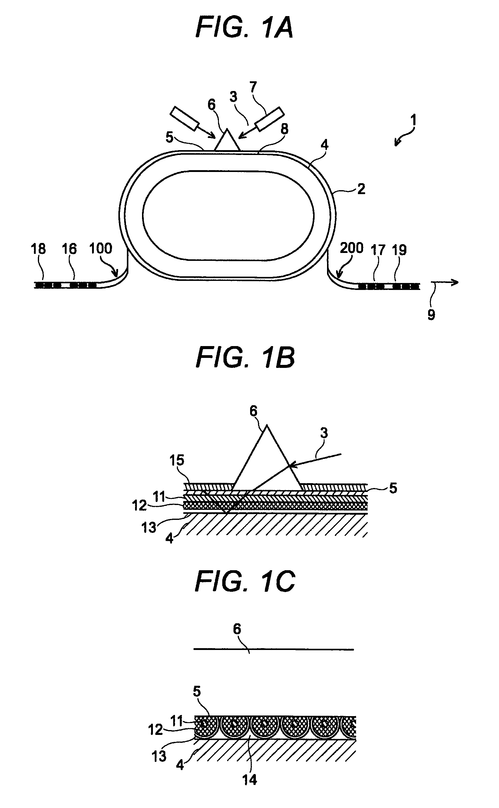
[0037]Referring to FIGS. 1A, 1B and 1C, the optical fiber laser 1 according to the present invention is characterized by the optical fiber laser 1 for oscillating a laser light 9 by introducing an excitation light 3 for exciting the rare earth elements into the optical fiber 2 doped partially by the rare earth elements, in which the optical fiber 2 is wrapped around the base member 4, and one part of the outer circumferential area of the wrapped optical fiber 2 is processed in order to form a flat surface 5, and one face of the prism 6 is made contacted to the flat surface 5, and the excitation light source 7 is directed to another surface of the prism 6.

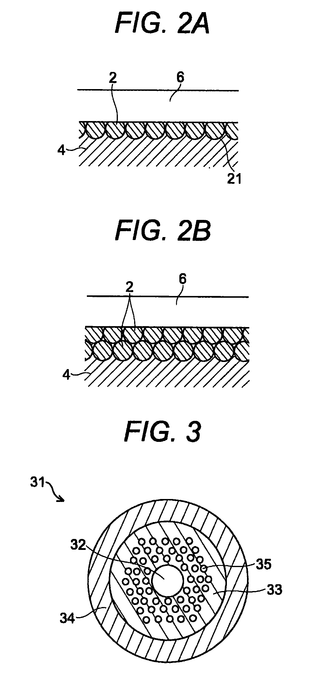
[0038]The cross-sectional shape of the base member 4 projected onto the vertical plane to the longitudinal axis of the base member 4 is identical at any place along the longitudinal direction of the base member 4. Thoug...


PUM


Abstract

To provide a low-cost, high reliability and high-powered operation enabled optical fiber laser, in the optical fiber laser for oscillating a laser light by introducing an excitation light for exciting the rare earth elements into the optical fiber doped partially by the rare earth elements, the optical fiber is wrapped around the base member, and one part of the outer circumferential area of the wrapped optical fiber is processed in order to form a flat surface, and one face of the prism is made contacted to the flat surface, and the excitation light is introduced to another surface of the prism.

Description

BACKGROUND OF THE INVENTION[0001]The present invention relates to an optical fiber laser that can be realized in lower cost, provided with higher reliability and enabled to be operated in high power.[0002]Development of higher powered and lower cost light sources are required for the application in laser material processing and medical equipment. In order to meet this requirement, optical fiber lasers are enabling technology for generating highly efficient single-mode laser lights easily.[0003]A conventional optical fiber laser uses such a double-clad type optical fiber 40 as shown in FIG. 4. The core region 41 of the double-clad type optical fiber 40 is doped by rare earth metals such as Nd, Yb, Er and Th. The clad region has a double structure in which an inner cladding region 42 having a refractive index lower than that of the core region 41 and an outer cladding region 43 having a refractive index lower than that of the inner cladding region 42 are included. The excitation light...

Claims


Application Information

Patent Timeline
Patent Type & Authority Patents(United States)
IPC IPC(8): H01S3/30
CPCH01S3/06704H01S3/06708H01S3/094003
Inventor HONGO, AKIHITOOHSONO, KAZUMASAYAO, BING
Owner HITACHI CABLE
Why Eureka
Try Eureka