[0008]The present invention is an autonomous vehicle collision / crossing warning system that provides for simple, inexpensive and decentralized installation, operation, and maintenance of a reliable vehicle collision / crossing warning system. The autonomous warning system preferably utilizes a single frequency TDM radio communication network with GPS
clock synchronization, time slot arbitration and connectionless UDP protocol to broadcast messages to all vehicles and components in the warning system. Adaptive localized mapping of components of interest within the warning system eliminates the need for centralized databases or coordination and control systems and enables new vehicles and warning systems to be easily added to the system in a decentralized manner. Preferably, stationary warning systems are deployed as multiple self-powered units each equipped to receive broadcast messages and to communicate with the other units by a low power RF channel in a redundant Master-Slave configuration. The communication schemes are preferably arranged for low
duty cycle operation to decrease
power consumption.
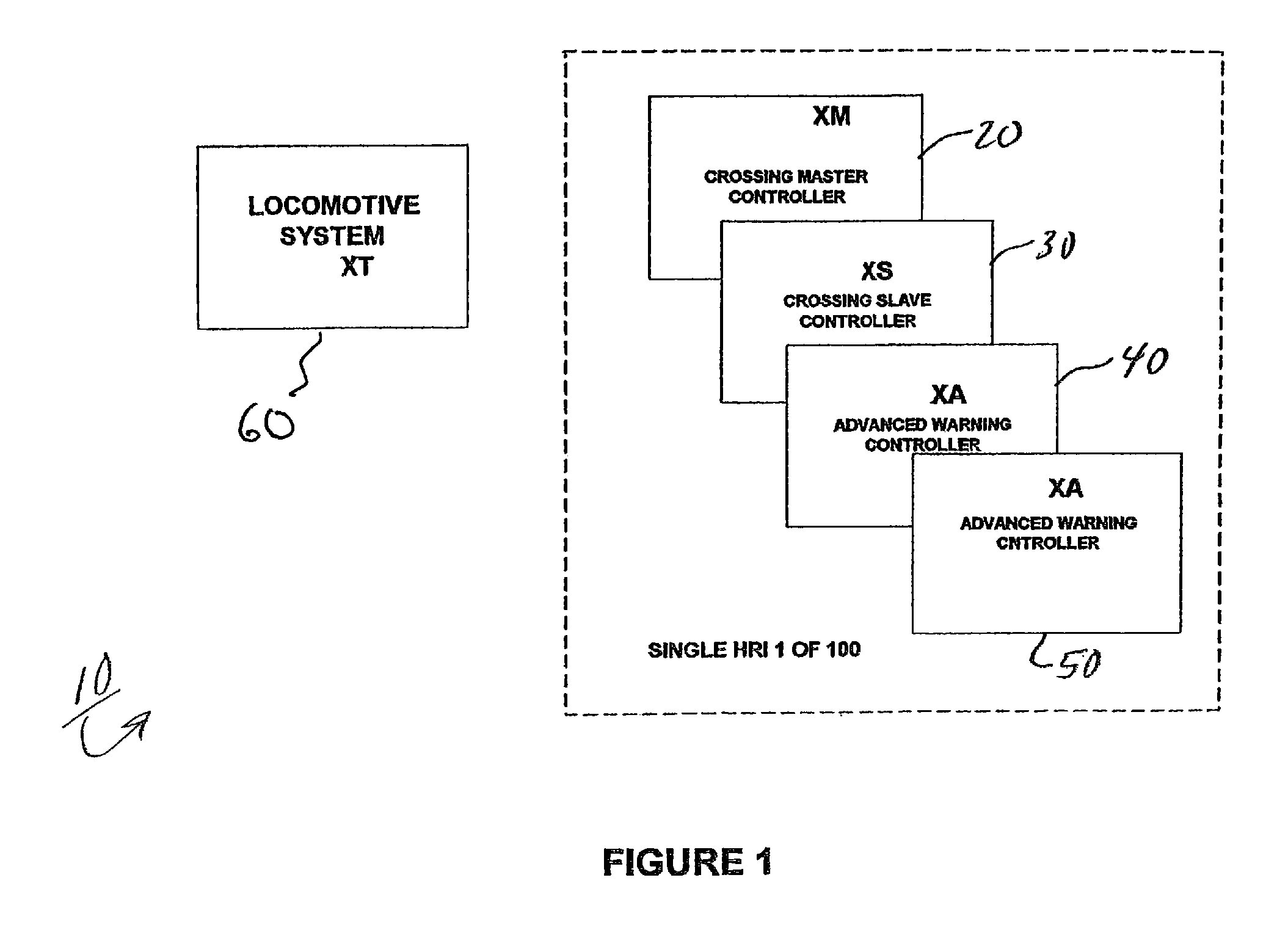
[0009]A preferred embodiment of the present invention is directed to a railroad crossing warning system that is low-cost and well-suited for use with
low volume highway-rail intersections. The autonomous railroad crossing warning system in accordance with this embodiment includes a tracking device, such as a
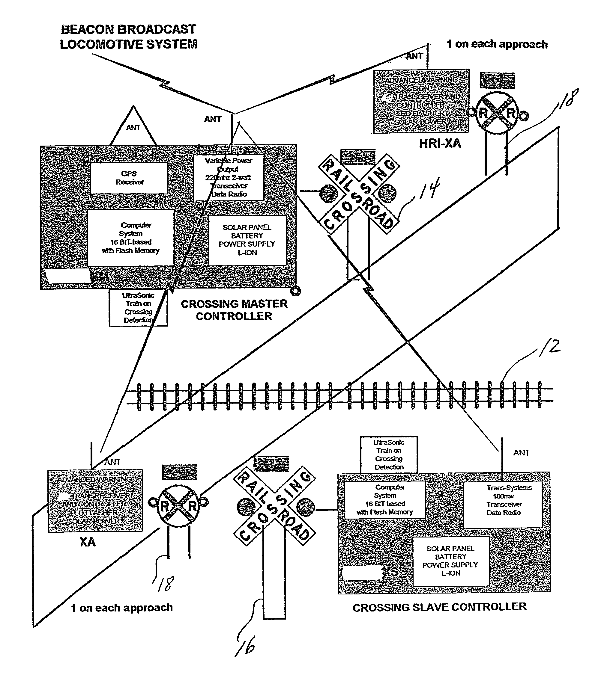
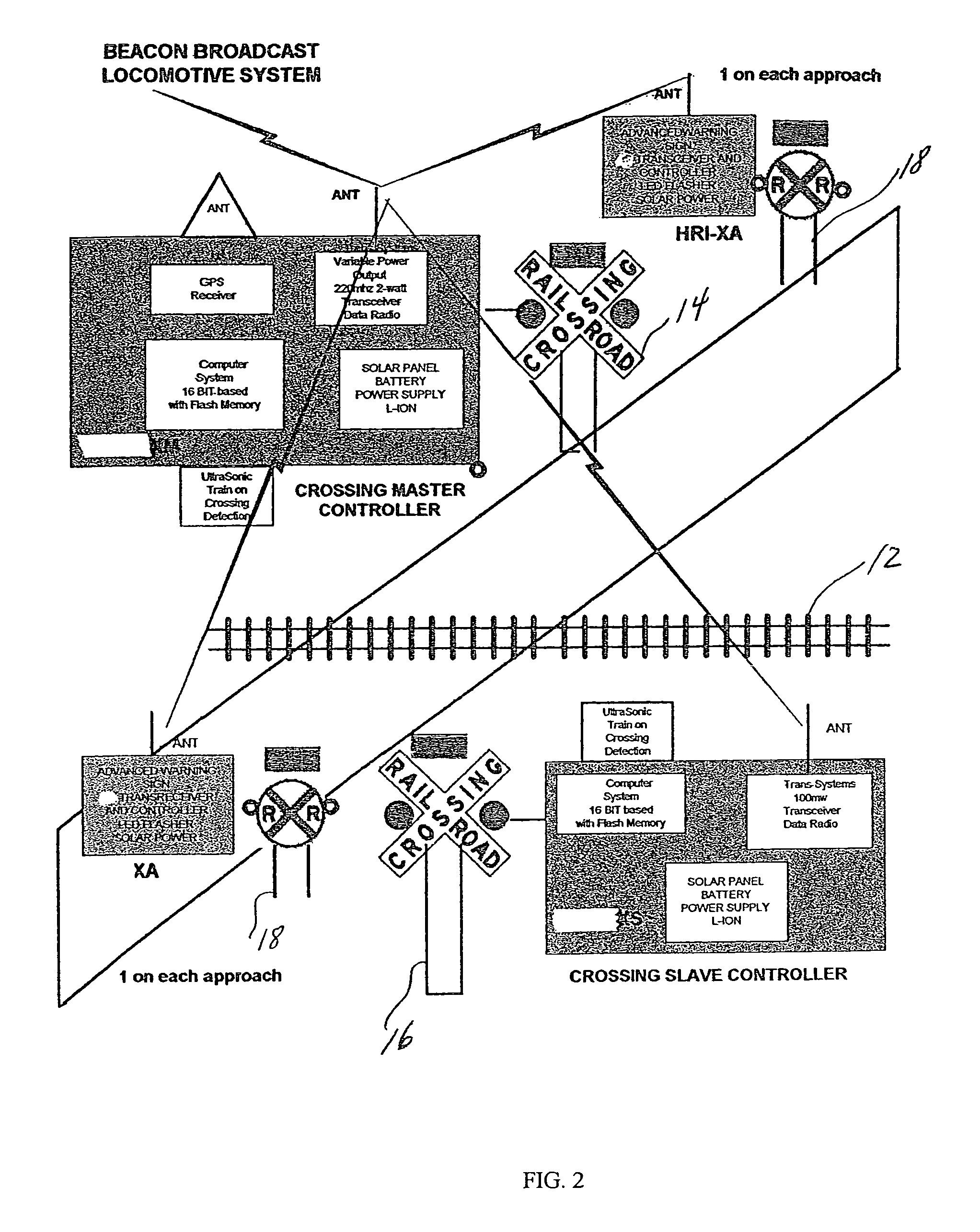
GPS receiver to calculate the position, velocity, and heading of a locomotive. A
GPS receiver is also provided at each railroad crossing to provide the location of the crossing to both passing locomotives and other crossings. The present invention also includes at least one
communication device on each locomotive and at each crossing that provides an autonomous single-frequency radio network utilizing time division multiplexed communication and synchronizes the radios with the GPS time
clock. Synchronization between transmitting and receiving of the radios on the network allows reduced
power consumption by the receivers. A communication protocol is used to ensure proper channel hopping and eliminate data collisions, which allows multiple devices to use one
radio frequency.
Software is provided at each railroad crossing to calculate locomotive
arrival time at the crossing based on
GPS data received through the radio network from the locomotive and activate the motorist warning devices at appropriate times. The
software supports multiple locomotives in the vicinity of the crossing and screens out locomotives that are on different courses and will not intersect the crossing. The two-way communication between locomotives and crossings will allow system status data from each crossing to be collected by passing locomotives and, if a crossing warning system is completely inoperable, automatically issuing a mayday broadcast to be received by passing vehicles and, optionally, having the passing locomotive telephone a centralized computer system with the location of the failure through a cellular phone on the locomotive. Preferably, data collection on the status and condition of the warning system is distributively collected by each locomotive. A handheld display / keyboard preferably is used to alert locomotive operators to upcoming crossings and also is used to enter locomotive length for purposes of
broadcasting this information.
[0010]The present invention preferably includes an autonomous locomotive detection system that does not impinge on the railroad right of way. In one embodiment of the present invention,
low frequency seismic sensors are used to awaken the
control system at each railroad crossing when a locomotive approaches within a certain distance of the crossing. Additional dual ultrasonic sensors may be used to monitor for the presence of components in the crossing, as well as when the locomotive has left the crossing. In another embodiment, dual magnetometers are used to monitor for presence of locomotives in or near the crossing. Another element of the present invention is the design allows for the use of
solar power to provide all system power needs at railroad crossings. Preferably, all of the hardware required for the crossing warning system is mounted on the existing cross buck posts or railroad ahead
warning signs so that additional site construction is minimized.
[0011]One feature of a preferred embodiment of the present invention is a self-adaptive
mapping algorithm that generates micro maps for each subsystem. The subsystems communicate with devices passing through their immediate environment and learn of other components in their environment and teach the passing devices information it does not know. This self-propagating
algorithm eliminates the need for a Master map at each subsystem. Passing devices generate Master maps that automatically update when passing through subsystems and teach subsystems of new components in their environment, thereby allowing passing vehicles to learn of upcoming components in the immediate environment.
[0012]A feature of the communication scheme of the present invention provides for a dual RF arrangement having broadcast cells surrounding each component in the warning system having a
radius of at least about 0.25 miles preferably using 2 W transmitters and local zones surrounding each units in a stationary warning system having a
radius of less than about 0.25 miles preferably using 100 mW transmitters. The local zone network preferably is synchronized by the Master unit with periodic GPS time stamps such that fewer GPS operations are required by the Slave units. The dual RF cellular arrangement with the arbitrated UDP (user datedgram protocol) communication scheme allows for vehicles to seamlessly join and leave cells as the move across stationary warning systems. In an alternate embodiment, vehicles can be equipped with collision avoidance
software and systems to inform moving vehicles of impending collisions with other vehicles. In one embodiment,
software in stationary devices makes decisions based upon analysis of the broadcast information to determine potential relevance and estimated arrival times of vehicles within a corresponding
cell. In a preferred embodiment, the local zone network utilizes phase and amplitude analysis of broadcast signals received by each of the units to differentiate valid locomotive broadcasts from extraneous triggers.
[0013]In a preferred embodiment of the application of a railroad crossing warning system, each locomotive is provided with a tracking (GPS) device on the locomotive to calculate position, speed and heading. Each crossing is also provided with a tracking (GPS) device to calculate at least an initial position and to establish
clock synchronization. The communication scheme between the locomotive and the crossing preferably allows for 2-way communication but does not require
handshake, acknowledgements or complete reception of all broadcasts in order to function properly. Preferably, multiple transceivers at the crossing provide 2+ levels of redundancy.

