
System and method for tissue specific MR imaging of metabolites using spectral-spatially formed stimulated echo

a tissue specific and stimulated echo technology, applied in the field of magnetic resonance imaging, can solve problems such as indistinct csi

Inactive Publication Date: 2010-08-10
GENERAL ELECTRIC CO
View PDF7 Cites 17 Cited by
  • Summary
  • Abstract
  • Description
  • Claims
  • Application Information

AI Technical Summary

Benefits of technology

"The invention is a magnetic resonance (MR) spectroscopy system that uses multiple gradient coils and an RF coil assembly to excite and detect MR signals. The system control programmed the RF coil assembly to emit a first RF pulse and a second RF pulse, with the second RF pulse being spectrally selective and the first RF pulse being spatially selective. The system control also programmed the RF coil assembly to emit a third RF pulse after a pre-defined time delay to generate a stimulated echo and detect MR signals resulting from the stimulated echo. The invention also includes a method for MR imaging that involves exciting a contrast agent and detecting MR signals resulting from the excitation of the contrast agent and metabolic products formed from the contrast agent. The computer program includes a sequence of instructions that causes the computer to request transmission of a spectral-spatial pulse and a follow-up RF pulse, as well as at least one read RF pulse to generate a stimulated echo. The system and method have advantages in improving the accuracy and resolution of MR spectroscopy and imaging."

Problems solved by technology

While CSI, as a sequence for imaging hyperpolarized substances, provides valuable information on tissue type and health of that tissue, prior art CSI does not distinguish where or when metabolic products are formed in a 13C-hyperpolarized metabolic imaging acquisition.

Method used


Image

  • System and method for tissue specific MR imaging of metabolites using spectral-spatially formed stimulated echo
  • System and method for tissue specific MR imaging of metabolites using spectral-spatially formed stimulated echo
  • System and method for tissue specific MR imaging of metabolites using spectral-spatially formed stimulated echo

Examples


Embodiment Construction

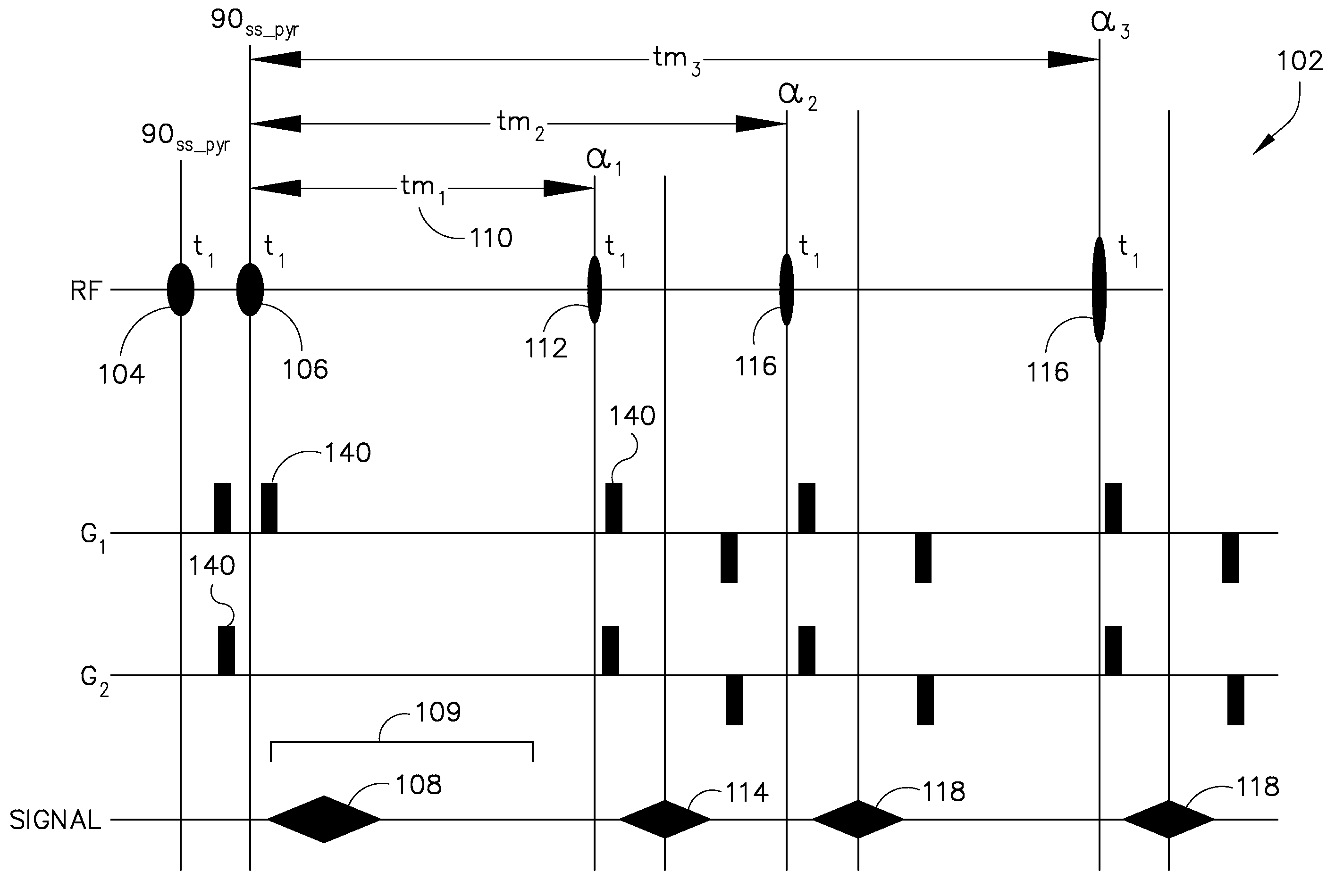
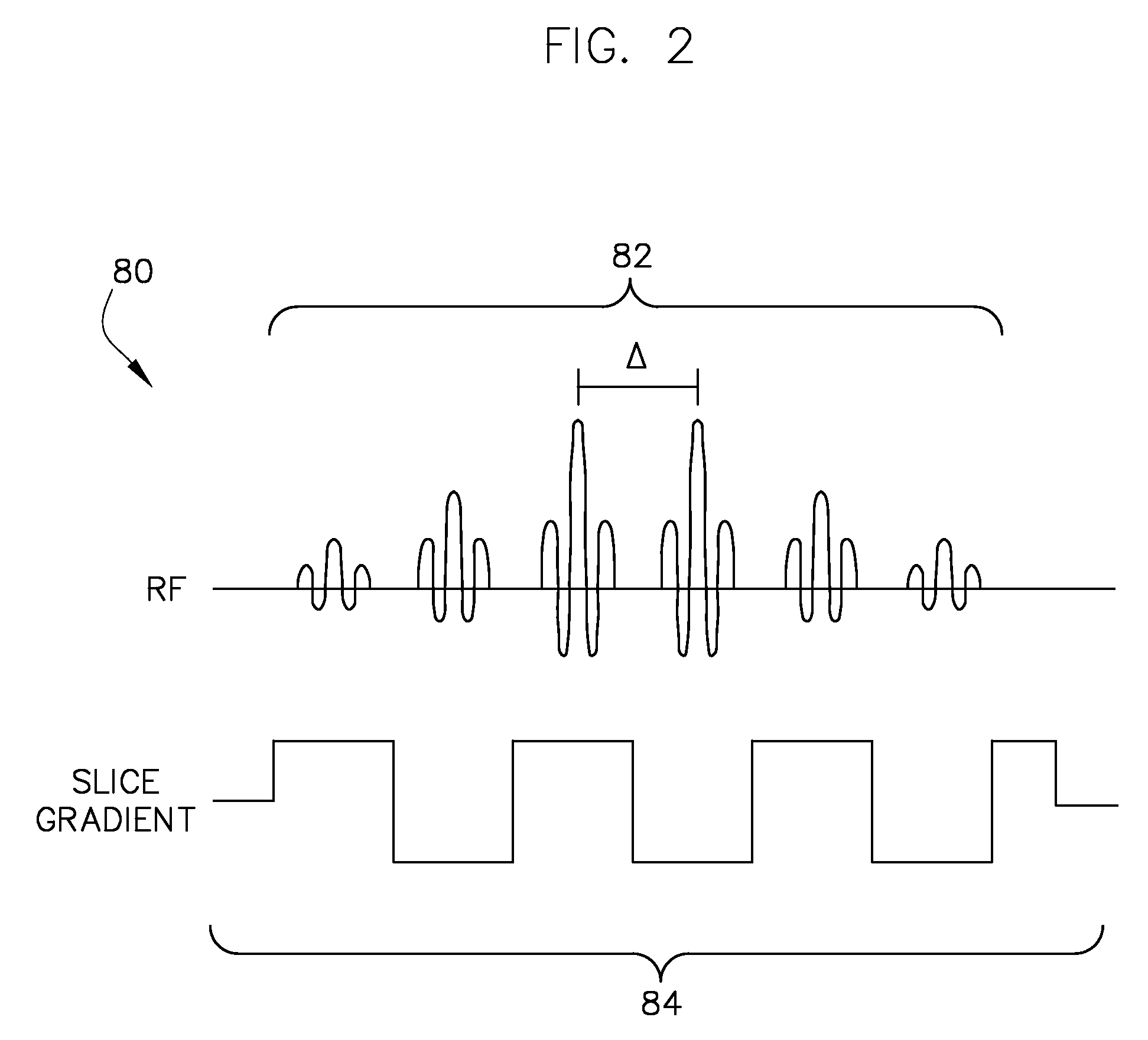
[0021]A system and method for slice-selectively exciting a resonant frequency for a metabolic reactant and for reading out a resulting metabolic process as a spectroscopic image is provided. In this regard, a pair of RF pulses may be emitted to spectral-spatially excite a frequency in a subject of interest for a specified metabolic reactant. Spectral-spatial radio frequency (RF) pulses may be used to create magnetization in a specific frequency profile without significantly affecting neighboring slices or nearby frequency ranges. A third RF pulse (either non-spectrally selective or spectrally selective) may then be emitted to generate a stimulated echo and excite a broad range of frequencies in the subject of interest for a plurality of metabolic products derived in vivo from the metabolic reactant. The signals resulting from these pulses are read in one or more of several well-known read out sequences.

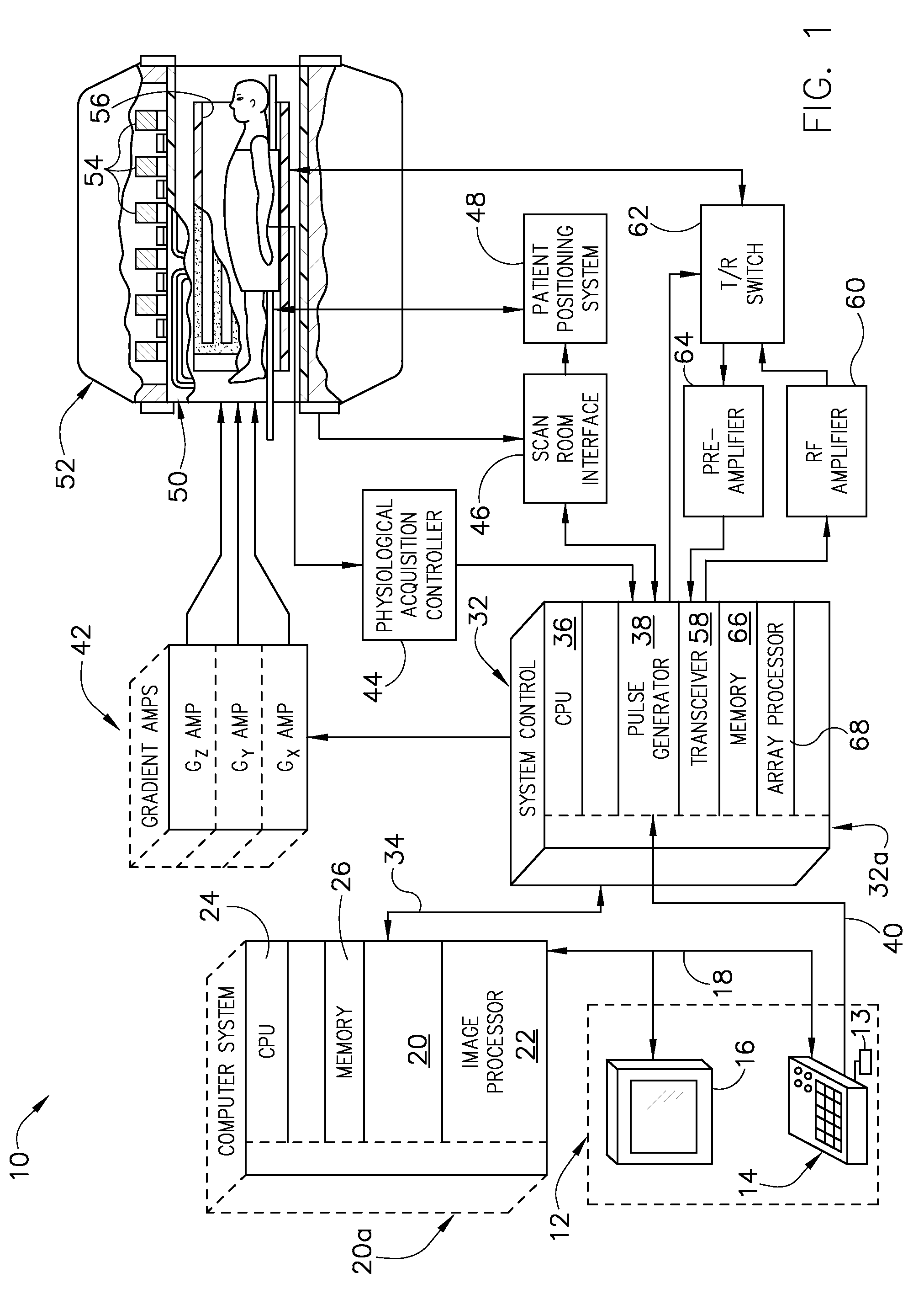
[0022]Referring to FIG. 1, the major components of an exemplary magnetic resonanc...


PUM


Abstract

A system for magnetic resonance (MR) spectroscopy includes a plurality of gradient coils positioned about a bore of a magnet and an RF coil assembly coupled to a pulse generator to emit RF pulse sequences and arranged to receive resulting MR signals from a subject of interest. A system control is also included in the MR spectroscopy system and is coupled to the plurality of gradient coils and the RF coil assembly. The system control is programmed to cause the RF coil assembly to emit a first RF pulse and a second RF pulse, wherein at least one of the first and second RF pulses is spectrally selective and at least one of the first and second RF pulses is spatially selective. The system control is also programmed to cause the RF coil assembly to emit a third RF pulse after a pre-defined time delay to generate a stimulated echo and detect MR signals resulting from the stimulated echo.

Description

BACKGROUND OF THE INVENTION[0001]Embodiments of the invention relate generally to magnetic resonance (MR) imaging, and more particularly, to tissue-specific MR imaging of metabolites using spectral-spatially formed stimulated echoes.[0002]When a substance such as human tissue is subjected to a uniform magnetic field (polarizing field B0), the individual magnetic moments of the spins in the tissue attempt to align with this polarizing field, but precess about it in random order at their characteristic Larmor frequency. If the substance, or tissue, is subjected to a magnetic field (excitation field B1) which is in the x-y plane and which has a frequency near the Larmor frequency, the net aligned moment, or “longitudinal magnetization”, Mz, may be rotated, or “tipped”, into the x-y plane to produce a net transverse magnetic moment Mt. A signal is emitted by the excited spins after the excitation signal B1 is terminated and this signal may be received and processed to form an image.[000...

Claims


Application Information

Patent Timeline
Patent Type & Authority Patents(United States)
IPC IPC(8): G01V3/00
CPCA61B5/055G01R33/485G01R33/5601G01R33/5617G01R33/4833
Inventor HURD, RALPH E.
Owner GENERAL ELECTRIC CO
Learn More