Compensated heat energy meter

a heat energy meter and compensation technology, applied in the field of calorimetry, can solve the problem that the heat meter no longer measures heat transfer accurately

Inactive Publication Date: 2010-08-17
ONICON INC
View PDF27 Cites 17 Cited by
  • Summary
  • Abstract
  • Description
  • Claims
  • Application Information

AI Technical Summary

Benefits of technology

[0014]If the TEM operating conditions (current, temperature, differential temperature, etc.) are carefully chosen the temperature drop on one of its surfaces will be a large fraction of the temperature rise of the other. The current direction through the TEM may be alternated so that each of the active surfaces in contact with the fluid is both heated at one time and cooled at another. These fac...

Problems solved by technology

As a result of any of these or other causes, the specific heat of the fluid can change from...

Method used


Image

  • Compensated heat energy meter
  • Compensated heat energy meter
  • Compensated heat energy meter

Examples


Embodiment Construction

[0026]In studying this Detailed Description, the reader may be aided by noting definitions of certain words and phrases used throughout this patent document. Wherever those definitions are provided, those of ordinary skill in the art should understand that in many, if not most instances, such definitions apply to both preceding and following uses of such defined words and phrases. At the outset of this Description, one may note that the terms “include” and “comprise,” as well as derivatives thereof, mean inclusion without limitation; the term “or,” is inclusive, meaning and / or.

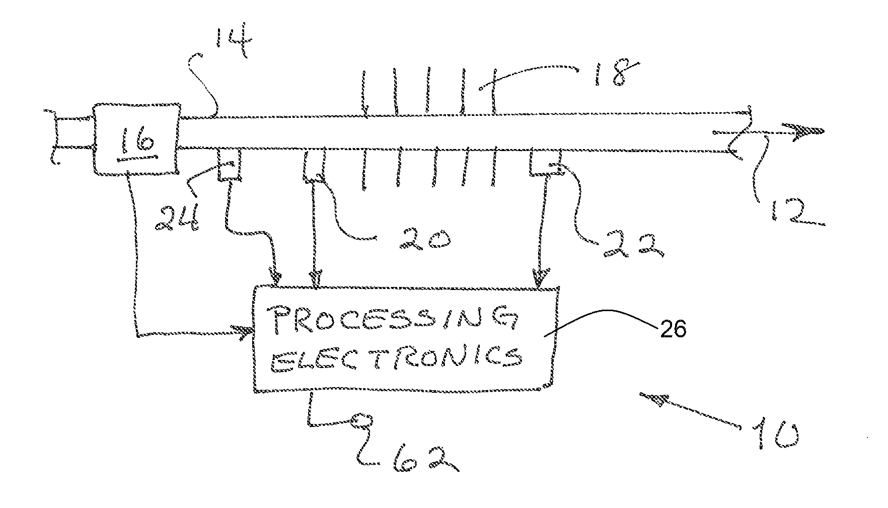
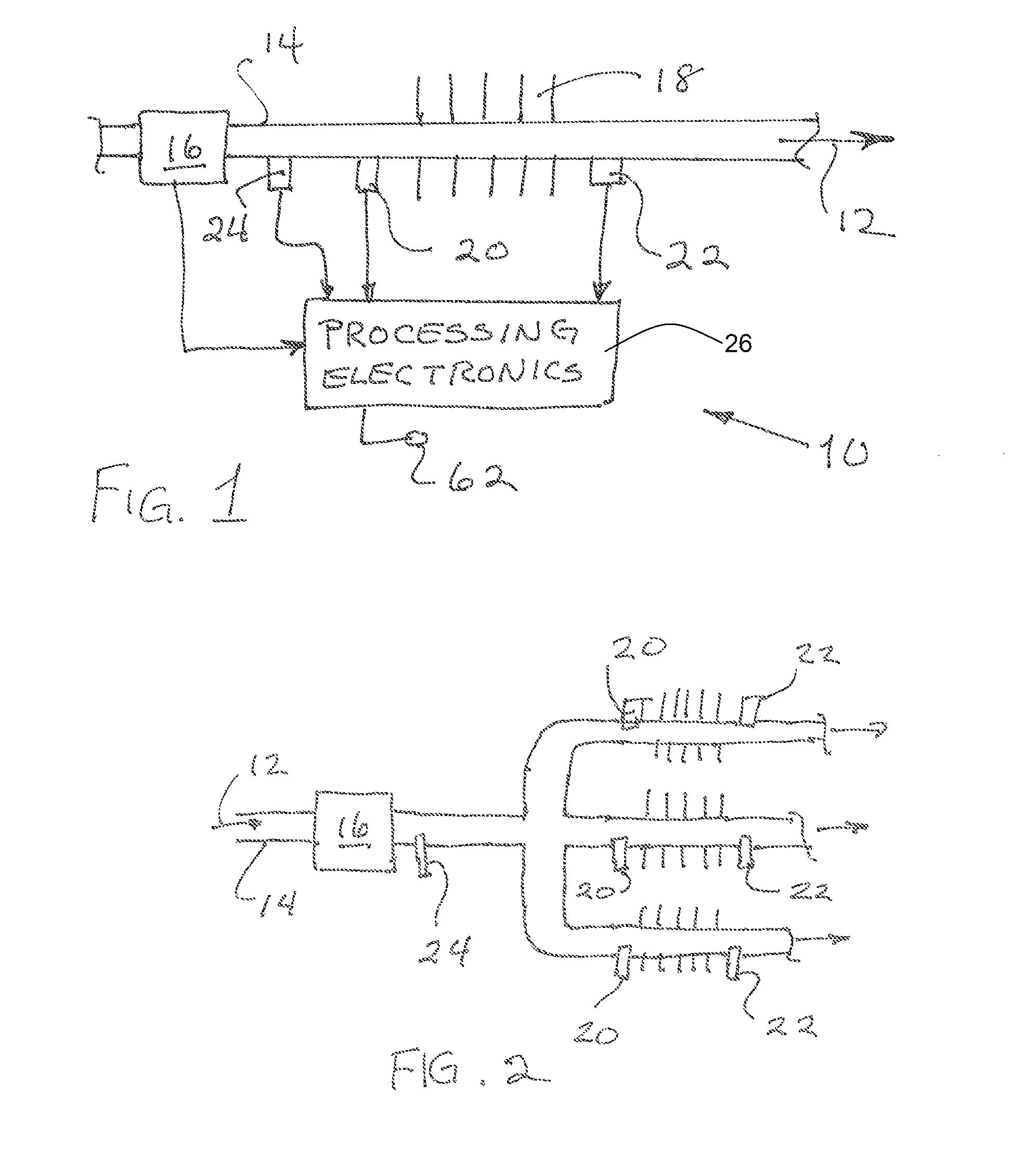
[0027]Turning now to FIG. 1, one finds a block diagram of an embodiment of a heat meter 10 of the invention. A flow rate of a working fluid 12, flowing through a pipe14 and a heat exchanger 18, is measured with a flow sensor 16. Inlet 20 and outlet 22 temperature sensors are used to measure the inlet and outlet temperatures of the heat exchanger 18, as is conventional in heat meters. This embodiment also provi...


PUM


Abstract

The specific heat of working fluids used in commercial heating systems commonly change with temperature and composition. Conventional heat metering systems assume a fixed value of the specific heat at a nominal temperature. This source of inaccuracy is removed by measuring the specific heat of a working fluid as a heating system operates and using the currently measured value in calculating the heat transferred. The real time specific heat measurement may be made by using a specific heat sensor having either a resistive heating element or a thermoelectric module.

Description

BACKGROUND OF THE INVENTION[0001]1. Field of the Invention[0002]This invention relates to calorimetry, and more specifically to calorimetric measurements made by combining flow rate and temperature signals.[0003]2. Background Information[0004]Heat meters, often referred to as BTU meters or net energy flow meters, determine the heat energy flow of a heat exchanger by measuring the flow rate of the heat exchanger fluid and the difference in temperature across the heat exchanger and by multiplying those measured quantities by factors selected to represent the specific heat of the fluid. The specific heat factor is generally selected based on a measured or presumed composition of the fluid and corrected for temperature.[0005]In a practical application, such as an apartment building where a heat metered hydronic heating system has been installed, the water-based working fluid composition may not remain constant. This may be because of loss of some of the working fluid and replacement of ...

Claims


Application Information

Patent Timeline
IPC IPC(8): G01K17/10G01N25/20
CPCG01K17/10
Inventor FELLER, MURRAY F
Owner ONICON INC
Why Eureka
Try Eureka