Device and method for separating magnetic or magnetizable particles from a liquid

a technology of magnetic or magnetizable particles and liquid separation, which is applied in the direction of high gradient magnetic separators, electrostatic separation, water/sludge/sewage treatment, etc., can solve the problems of high material consumption, inability to handle very large numbers of samples by purely manual handling, and devices that are not suitable for removing magnetic particles from reaction vessels, etc., to avoid cross contamination

Active Publication Date: 2010-08-17
CHEMAGEN BIOPOLYMER TECH AKTIENGES
View PDF26 Cites 23 Cited by
  • Summary
  • Abstract
  • Description
  • Claims
  • Application Information

AI Technical Summary

Benefits of technology

[0027]It is furthermore provided that a replaceable envelope, which can be pulled off, is slipped on each bar in order to avoid cross-contamination between different liquid samples. For this purpose, a special device is preferably provided which enables automatic discarding of the used envelopes and providing and mounting of new envelopes.
[0028]By arranging a permanent magnet, which may also be composed of a plurality of individual magnets, a substantially homogeneous magnetic field is produced between the poles of the limbs. In this way it is possible to dispose a larger number of bars, for instance in several rows, with the magnetic field being approximately of the same size at each of the bars; this is of particular advantage with a view to high-throughput processes. A further advantage of the devices according to the invention is that the magnetic particles—in the activated state—accumulate substantially at the tips of the bars.
[0048]In particular, the holders may also be configured such that they can be used for carrying out shaking movements. The constructional measures required therefor are basically known to the person skilled in the art. It is furthermore provided that both the head piece and the holder may be movable and utilized to carry out shaking movements. It is thereby possible to achieve an especially effective intermixing of the sample liquid when the bars are immersed therein.
[0050]In particular, the above-mentioned holder may be a component of a program-controlled laboratory robot system. Preferably, the holder is adjusted such that a plurality of individual ones of the containers or groups of such containers, particularly microtiter plates, are alternately moved into a position below the bars and subsequently, after a predeterminable time interval, again into a position which is outside the region below the bars. This allows a high sample throughput.
[0071]To improve purity and yield, it may be advantageous to release the particles into the liquid, following step d), by deactivating the magnetic field, to mix the liquid and subsequently to re-accumulate the particles on the bars by activating the magnetic field. Intermixing can be accomplished, for example, by rotation of the bars or by agitating the holder or / and the head piece.

Problems solved by technology

This is extremely important for applications in molecular-genetic studies or in the field of medical diagnostics, for example, as it is practically impossible to cope with very large numbers of samples by purely manual handling.
These devices are, however, not suitable for removing the magnetic particles from a reaction vessel.
This is a disadvantage, as it entails high material consumption (disposable pipette tips).
Furthermore, it is unavoidable that individual magnetic particles are also sucked off, thus leading to a high error rate.
Other errors can be caused by liquids dripping down, leading to cross-contamination.
A disadvantage of this device is that the magnetic field produced by the excitation coil is not sufficiently homogenous so that the individual bars, depending on their position within the ring-shaped excitation coil, are magnetized to a different extent.
This disadvantage is particularly eminent where a large number of bars is required.
In addition, the excitation coil requires a relatively large space, which results in constructional limitations.
Above all, the known devices are not suitable for simultaneous treatment of large numbers of samples as is required in high-throughput applications (e.g., microtiter plates with 364 or 1536 wells).

Method used


Image

  • Device and method for separating magnetic or magnetizable particles from a liquid
  • Device and method for separating magnetic or magnetizable particles from a liquid
  • Device and method for separating magnetic or magnetizable particles from a liquid

Examples


Embodiment Construction

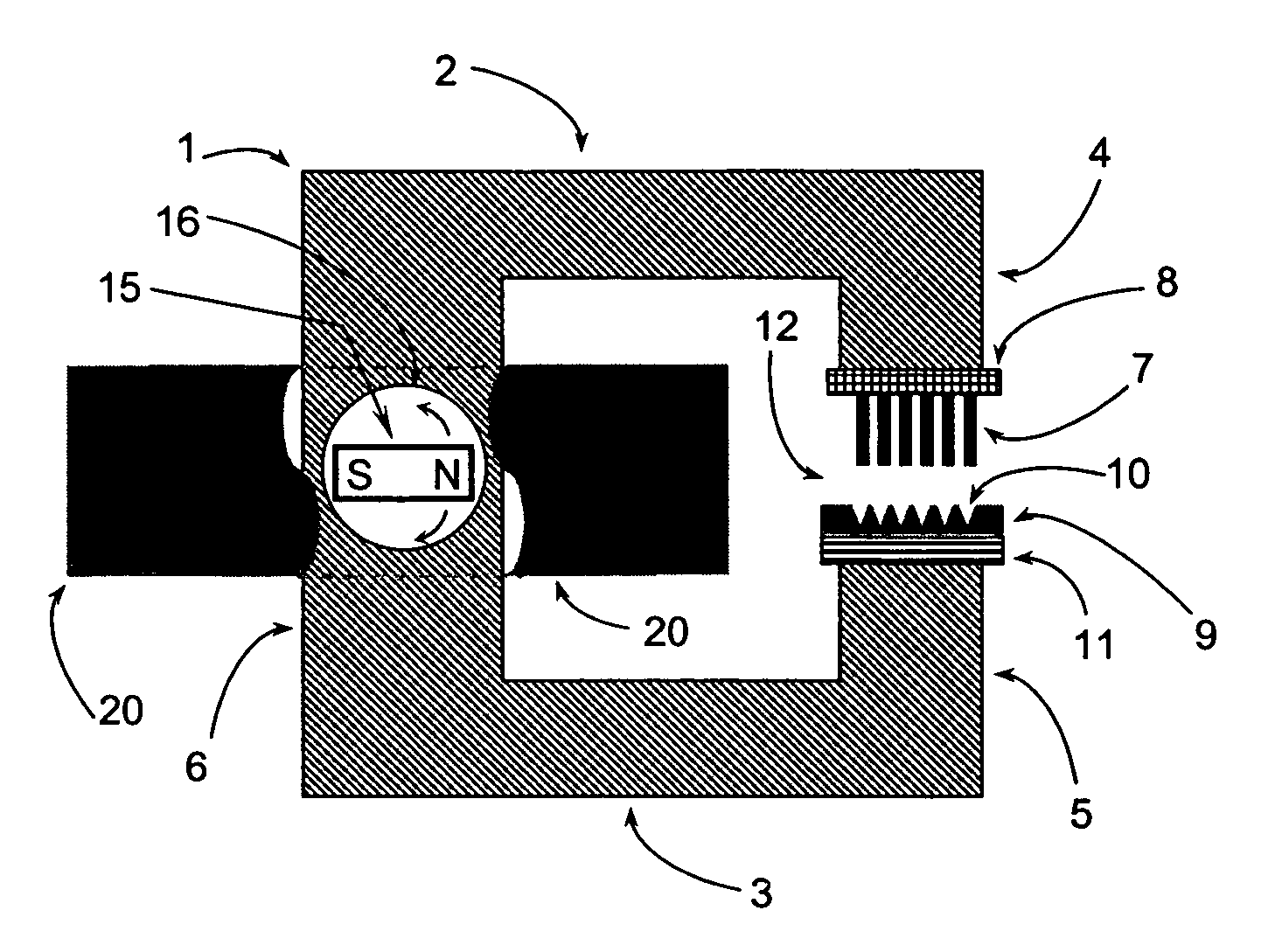
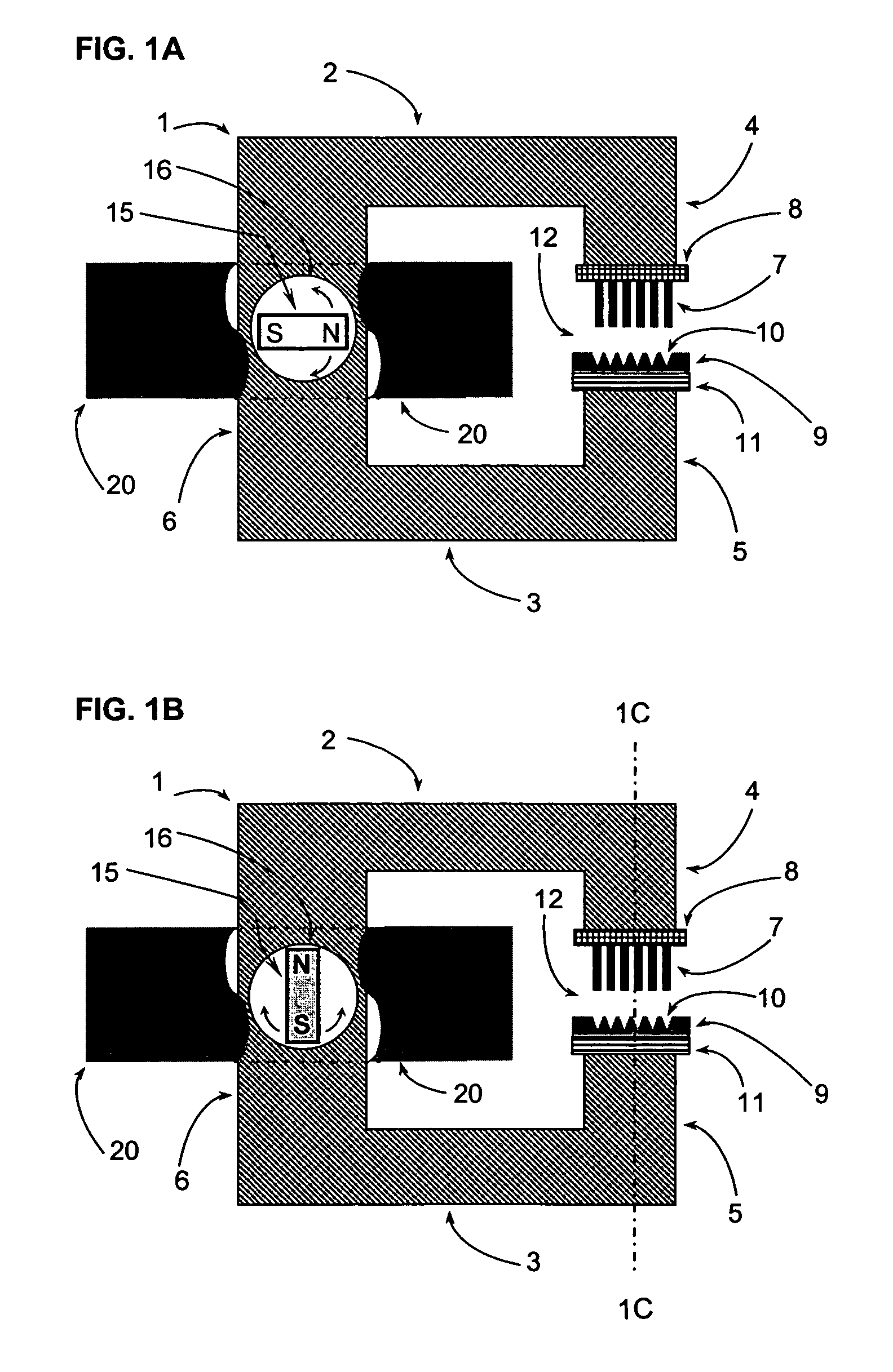
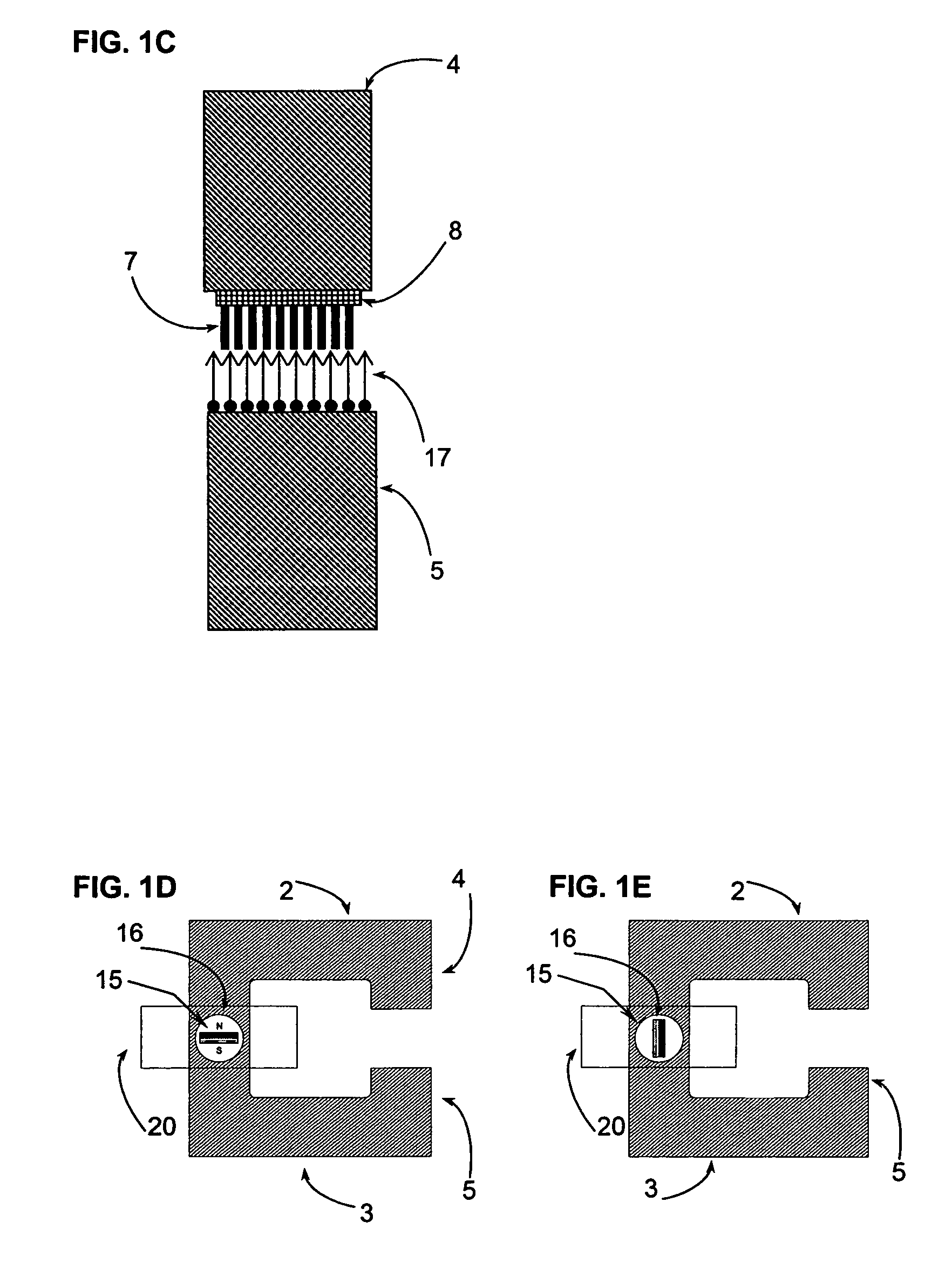
[0107]FIGS. 1A and 1B depict an embodiment of a device according to the invention, in side view. The device (1) has two magnetizable limbs (2, 3) of a magnetic circuit, the limbs being connected with each other in the region (6). At the opposite end of the limbs are the two poles (4, 5), with an air gap (12) located therebetween. The pole (4) of the upper limb (2) carries a head piece (8) with bars (7) attached thereto. Below the bars there is a holder (11) which is connected with the pole (5) of the other limb (3) or is at least in contact therewith. On the holder, there is arranged a sample container (9) having a plurality of depressions (10) for receiving liquid samples—for example, fixed on the holder (11) in a detachable manner.

[0108]On the side opposite of the air gap (12), in the region (6) connecting the two limbs, there is a recess (16), wherein a bar-shaped or cuboid permanent magnet (15) is rotatably arranged. Around the region of the permanent magnet there is arranged a ...


PUM

PropertyMeasurementUnit
volumeaaaaaaaaaa
magnetic fieldaaaaaaaaaa
soft-magneticaaaaaaaaaa

Abstract

A device is provided to separate magnetic or magnetizable particles from a liquid by using a magnetic field. The device includes two limbs made of a soft-magnetic material. An air gap is provided between be two poles of the limbs. The air gap can receive one or more liquid containers. A head piece is arranged in a fixed or detachable manner on one of the two poles. One or more magnetizable bars are disposed in a fixed or movable manner on the head piece, in the vertical direction. One or more permanent magnets are arranged in a movable manner on at least one point of the device, such that a magnetic field can be produced between the two poles and the magnetic field can be activated or deactivated by moving the magnet(s). The region of the device where the movable magnet(s) are arranged is at least partially surrounded by a material that screens the magnetic field.

Description

CROSS-REFERENCE TO RELATED APPLICATIONS[0001]This application is a U.S. National Phase (Section 371) of International Application No. PCT / EP2004 / 007308, filed Jul. 5, 2004, which was published in the German language on Jan. 20, 2005, under International Publication No. WO 2005 / 005049 A1, and the disclosure of which is incorporated herein by reference.BACKGROUND OF THE INVENTION[0002]The invention relates to devices for separating magnetic or magnetizable particles from liquids by a magnetic field produced by one or more permanent magnets.[0003]The invention further relates to methods for separating magnetic or magnetizable particles from liquids by a magnetic field produced by one or more permanent magnets. The devices and methods can be used, for example, for applications in biochemistry, molecular genetics, microbiology, medical diagnostics and forensic medicine.[0004]Methods based on magnetic separation using specifically binding, magnetically attractable particles are increasing...

Claims


Application Information

Patent Timeline
Patent Type & Authority Patents(United States)
IPC IPC(8): B03C1/033B03C1/01B03C1/06B03C1/28
CPCB03C1/286B03C1/288B03C1/01B03C1/06B03C2201/26
Inventor BRASSARD, LOTHAR
Owner CHEMAGEN BIOPOLYMER TECH AKTIENGES
Why Eureka
Try Eureka