Hydraulic pressurizer system

a technology of hydraulic pressure and pressurizing system, which is applied in the direction of positive displacement liquid engine, piston pump, machine/engine, etc., can solve the problem of delay in the rise of hydraulic pressure applied by the electrical oil pump, and achieve the effect of agitating and dispersing effectively, cost-effective manufacturing and effective

Inactive Publication Date: 2010-08-24
HONDA MOTOR CO LTD
View PDF19 Cites 31 Cited by
  • Summary
  • Abstract
  • Description
  • Claims
  • Application Information

AI Technical Summary

Benefits of technology

[0006]In the hydraulic pressurizer system, preferably, the cleaning operation is realized by a program installed on the control unit, and the period of time for which the cleaning operation is executed is a short period of time, which is administered by a timer of the program. In particular, it is preferable that the period of time for which the cleaning operation is executed be equal to or shorter than the period of the rotation of the electrical motor.
[0011]This cleaning operation is executed specifically before the execution of the control for stopping the drive source (engine). As a result, the hydraulic pressure applied by the electrical oil pump is elevated promptly to a sufficient level before the hydraulic pressure by the mechanical oil pump decreases. Therefore, it is possible to supply the required hydraulic pressure to the ratio-change mechanism continuously when the source of the hydraulic pressure is switched from the mechanical oil pump to the electrical oil pump.
[0012]The cleaning operation is realized by a program installed on the control unit, and the time period for which the cleaning operation is being executed is a short period of time, which is administered by a timer of the program. This time period is set equal to or shorter than the time that the electrical motor takes for one rotation, so the cleaning operation never affects the idling-elimination control.
[0013]The hydraulic pressurizer system according to the present invention, whose electrical motor is a three-phase brush-less sensor-less motor, is energy-efficient and is manufactured cost-effectively.
[0014]Furthermore, by the provision of the recirculation circuit, which comprises an oil passage that connects the outlet side and the inlet side of the electrical oil pump and a relief valve, as hydraulic oil discharged from the electrical oil pump circulates through the recirculation circuit, air bubbles are agitated and dispersed effectively.

Problems solved by technology

If air enters the hydraulic circuit as bubbles while the engine is operating, i.e., while the electrical oil pump is not operating, then when the electrical oil pump is restarted, it may suck up the bubbles and skid momentarily, resulting in a delay in the rise of the hydraulic pressure applied by the electrical oil pump.

Method used


Image

  • Hydraulic pressurizer system
  • Hydraulic pressurizer system
  • Hydraulic pressurizer system

Examples


Embodiment Construction

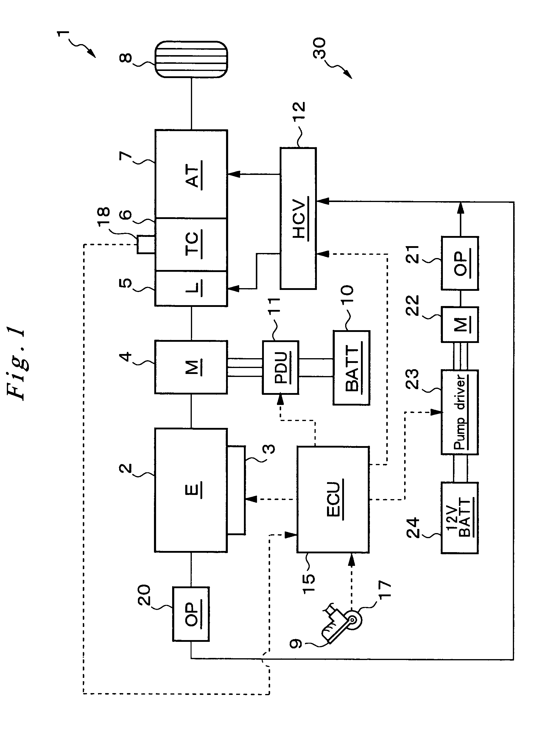
[0022]Now, preferred embodiments according to the present invention are described in reference to the drawings. At first, the construction of the drive system of a hybrid vehicle, which is equipped with a hydraulic pressurizer system according to the present invention, is described in reference to FIG. 1.

[0023]This hybrid vehicle 1 comprises an engine 2 and an electricity-generating motor (referred to as motor generator) 4 as drive sources, which are connected in series. The vehicle also comprises a torque converter 6, which is connected to the drive sources and equipped with a lock-up clutch 5, and an automatic ratio-change mechanism 7, whose output shaft is connected to drive wheels 8. In this arrangement, the driving force applied alternatively from the engine 2 or the motor generator 4 or simultaneously from these two is transmitted through the torque converter 6 with the lock-up clutch 5 and the automatic ratio-change mechanism 7 to the wheels 8, driving the hybrid vehicle 1, w...


PUM


Abstract

A hydraulic pressurizer system (30) comprises a drive source (an engine 2 and a motor generator 4), which drives a hybrid vehicle (1), a mechanical oil pump (20), which is driven by the drive source, an electrical motor (22), which is activated by a 12V battery (24), an electrical oil pump (21), which is driven by the electrical motor (22), and a control unit (15), which activates the electrical motor (22). The pressurizer further comprises a ratio-change mechanism (7), which is activated by hydraulic oil supplied by the mechanical oil pump (20) and by the electrical oil pump (21) to establish a speed change ratio, at which the rotational driving force of the drive source is transmitted to wheels (8) with a rotational speed change. For executing a control for stopping the drive source, the control unit (15) executes a cleaning operation, which operates the electrical oil pump (21) for a predetermined time before the stopping of the drive source.

Description

FIELD OF THE INVENTION[0001]The present invention relates to a hydraulic pressurizer system, which is used, for example, in a hybrid vehicle and which supplies hydraulic oil to the ratio-change mechanism and the like by an electrically driven oil pump while the engine is not in operation.BACKGROUND OF THE INVENTION[0002]A hybrid vehicle is driven by a drive source that is a combination of an engine and a motor capable of electricity generation (motor generator), and such a vehicle has been developed for improving fuel efficiency and for reducing exhaust gas in environmental protection. Typically, a hybrid vehicle is controlled for stopping the engine when the vehicle stops in so-called idling-elimination. In this case, when the engine stops, the mechanically driven oil pump, which has been in operation for supplying hydraulic oil, for example, to the ratio-change mechanism, also stops. Therefore, for complementarity, an electrically driven oil pump or electrical oil pump is provided...

Claims


Application Information

Patent Timeline
Patent Type & Authority Patents(United States)
IPC IPC(8): F16H57/04B60K6/485B60K6/547B60L50/16B60W10/04B60W10/06B60W10/08B60W10/10B60W10/11B60W10/30B60W20/00F02D29/00F16H57/02F16H61/00F16H61/68
CPCB60K6/48F16H61/0031F16H61/0025F16H2061/004Y02T10/6221Y02T10/62
Inventor KITANO, KAZUHIKOMIYAMOTO, OSAHIDEKANEDA, TOMOHISA
Owner HONDA MOTOR CO LTD
Why Eureka
Try Eureka