Path module for a linear motor, modular linear motor system and method to control the same

a linear motor and modular technology, applied in the field of motors, can solve the problems of limited maximum force obtainable from a linear motor, inconvenient cable loop connection of moving and stationary elements, and limit the flexibility with which a system can be designed, and achieve the effect of facilitating independent control of the windings

Inactive Publication Date: 2010-08-24
ROCKWELL AUTOMATION
View PDF34 Cites 13 Cited by
  • Summary
  • Abstract
  • Description
  • Claims
  • Application Information

AI Technical Summary

Benefits of technology

[0017]According to another aspect, the windings of a module are non-interlaced. That is, the windings are positioned side-by-side in a non-overlapping manner. The module also has a separate amplifier associated with each of the windings. Each amplifier is operative to control energization of its associated windings so as to facilitate independent control of the windings in the module.

Problems solved by technology

The maximum force obtainable from a linear motor is limited by the allowable temperature rise in the armature windings.
The need for a cable loop connecting moving and stationary elements is inconvenient, and limits the flexibility with which a system can be designed.
In addition, the wiring harness adds additional weight to the moving element of the linear motor.
Furthermore, manufacturing of a linear motor employing a wiring harness incurs additional cost of material and assembly labor.
The cost of producing a linear motor is increased when each assembly is custom designed to a users needs, with new tooling required for each such design.
The stocking of common parts also decreases overall cost of manufacturing since materials will be bought in bulk from common suppliers.
However, the incorporation of such a coil has the disadvantage of increasing costs because of the complexity of assembly and material expenses.
Furthermore, while the use of the settable resin prevents the occurrence of eddy currents, the thermal conductivity of the settable resin is significantly less than that of metals which it replaces and thus reduces the power dissipation capacity of the linear motor.
In a permanent magnet linear motor, the available magnetic field intensity is limited by the field strength of available motor magnets.

Method used


Image

  • Path module for a linear motor, modular linear motor system and method to control the same
  • Path module for a linear motor, modular linear motor system and method to control the same
  • Path module for a linear motor, modular linear motor system and method to control the same

Examples


Embodiment Construction

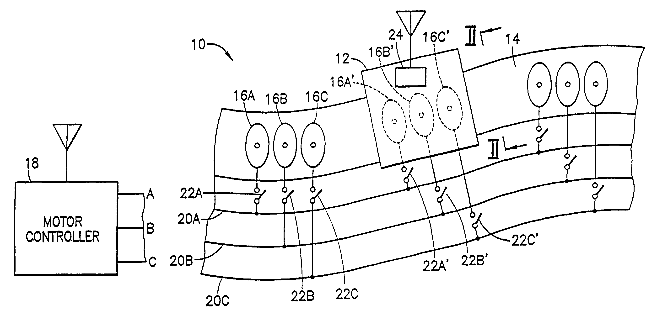
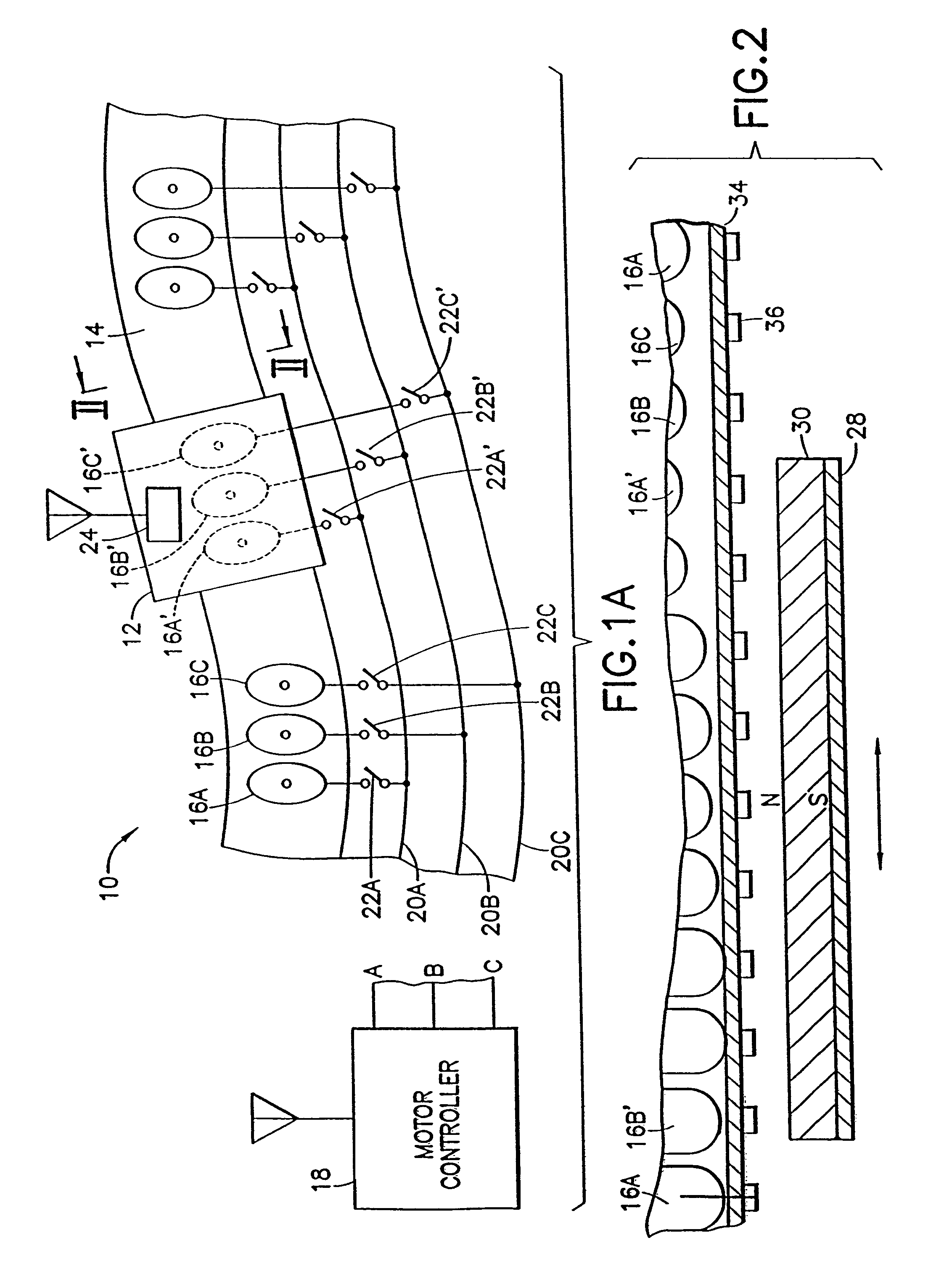
[0055]Referring to FIG. 1A, there is shown, generally at 10, a linear motor according to an aspect of the invention. A movable stage 12 is supported and guided in any convenient manner along a path 14. Path 14 includes therein repeating sets of three armature windings 16A, 16B and 16C for receiving, respectively, phases A, B and C of three-phase drive power produced by a motor controller 18. Phase A of the drive power from motor controller 18 is connected on a phase-A conductor 20A to terminals of normally-open phase-A switches 22A. Each phase-A switch is connected to its associated phase-A armature winding 16A. Similarly, phase-B and phase-C drive power are connected on phase-B and phase-C conductors 20B and 20C to terminals of phase-B and phase-C switches 22B and 22C, respectively. Armature windings 16A, 16B and 16C of each set may be noninterleaved. That is, they lie side by side, not overlapping as is the case in some prior art linear motors.

[0056]Switches 22A, 22B and 22C remai...


PUM


Abstract

A path module for a linear motor system includes a controller coupled to one or more amplifiers that are operative to control associated windings in the module. The controller receives control information via a communications link. The controller controls the amplifier based on the received control information so as to selectively energize the associated windings in the module. In one aspect, a plurality of such modules may be connected together to form a path along which one or more stages are moveable according to energization of the windings in the path.

Description

CROSS REFERENCE TO RELATED APPLICATIONS[0001]This application is a continuation of U.S. patent application Ser. No. 11 / 243,160, filed Oct. 4, 2005, entitled “PATH MODULE FOR A LINEAR MOTOR, MODULAR LINEAR MOTOR SYSTEM AND METHOD TO CONTROL SAME”, which is a continuation of U.S. patent application Ser. No. 10 / 909,439, filed Aug. 2, 2004, entitled “PATH MODULE FOR A LINEAR MOTOR, MODULAR LINEAR MOTOR SYSTEM AND METHOD TO CONTROL SAME”, which is a continuation of U.S. patent application Ser. No. 09 / 884,410, filed Jun. 19, 2001, entitled “PATH MODULE FOR A LINEAR MOTOR, MODULAR LINEAR MOTOR SYSTEM AND METHOD TO CONTROL SAME”, which is a continuation-in-part of U.S. patent application Ser. No. 09 / 415,166 entitled “CLOSED-PATH LINEAR MOTOR”, which is a continuation of U.S. patent application Ser. No. 09 / 069,324 entitled “CLOSED-PATH LINEAR MOTOR” filed Apr. 29, 1998, now U.S. Pat. No. 5,994,798, which is a continuation-in-part of U.S. patent application Ser. No. 09 / 031,009 entitled “LINEA...

Claims


Application Information

Patent Timeline
Patent Type & Authority Patents(United States)
IPC IPC(8): H02P7/00
CPCH02P25/06
Inventor FAIZULLABHOY, MUSTANSIRCHITAYAT, ANWARCARDAMONE, JOSEPH
Owner ROCKWELL AUTOMATION
Why Eureka
Try Eureka