
Adaptive signal-feed-forward circuit and method for reducing amplifier power without signal distortion

a technology of adaptive signal and amplifier power, applied in the field of amplifier circuitry, can solve the problems of power converter circuitry not being able to provide the power required by the amplifier, power requirements of the amplifier load vary, and power converters may not be power efficient, so as to achieve the effect of reducing power

Active Publication Date: 2010-08-24
TEXAS INSTR INC
View PDF8 Cites 92 Cited by
  • Summary
  • Abstract
  • Description
  • Claims
  • Application Information

AI Technical Summary

Benefits of technology

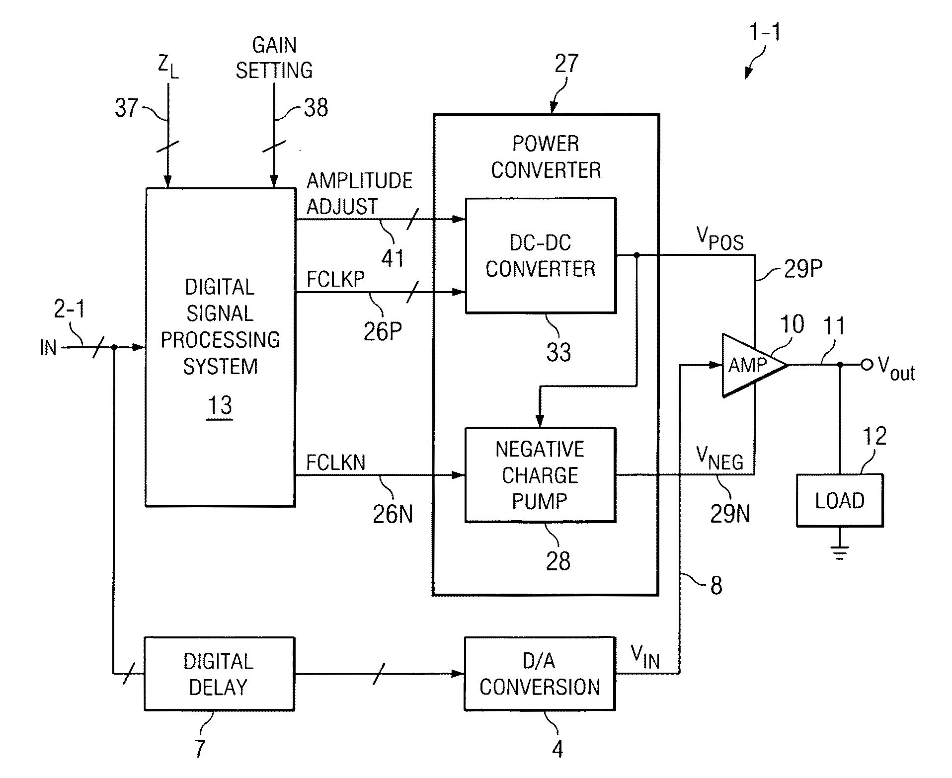
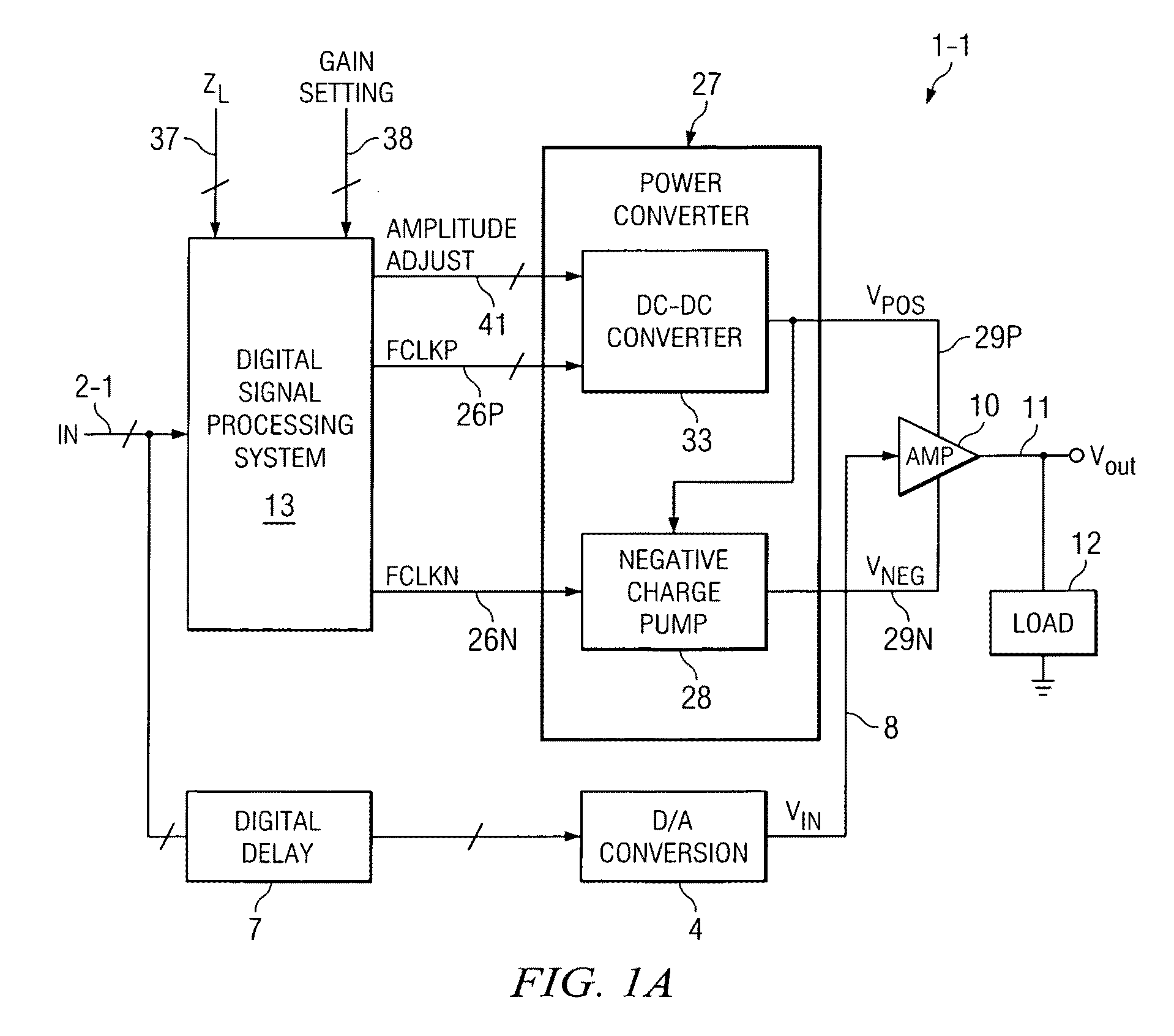
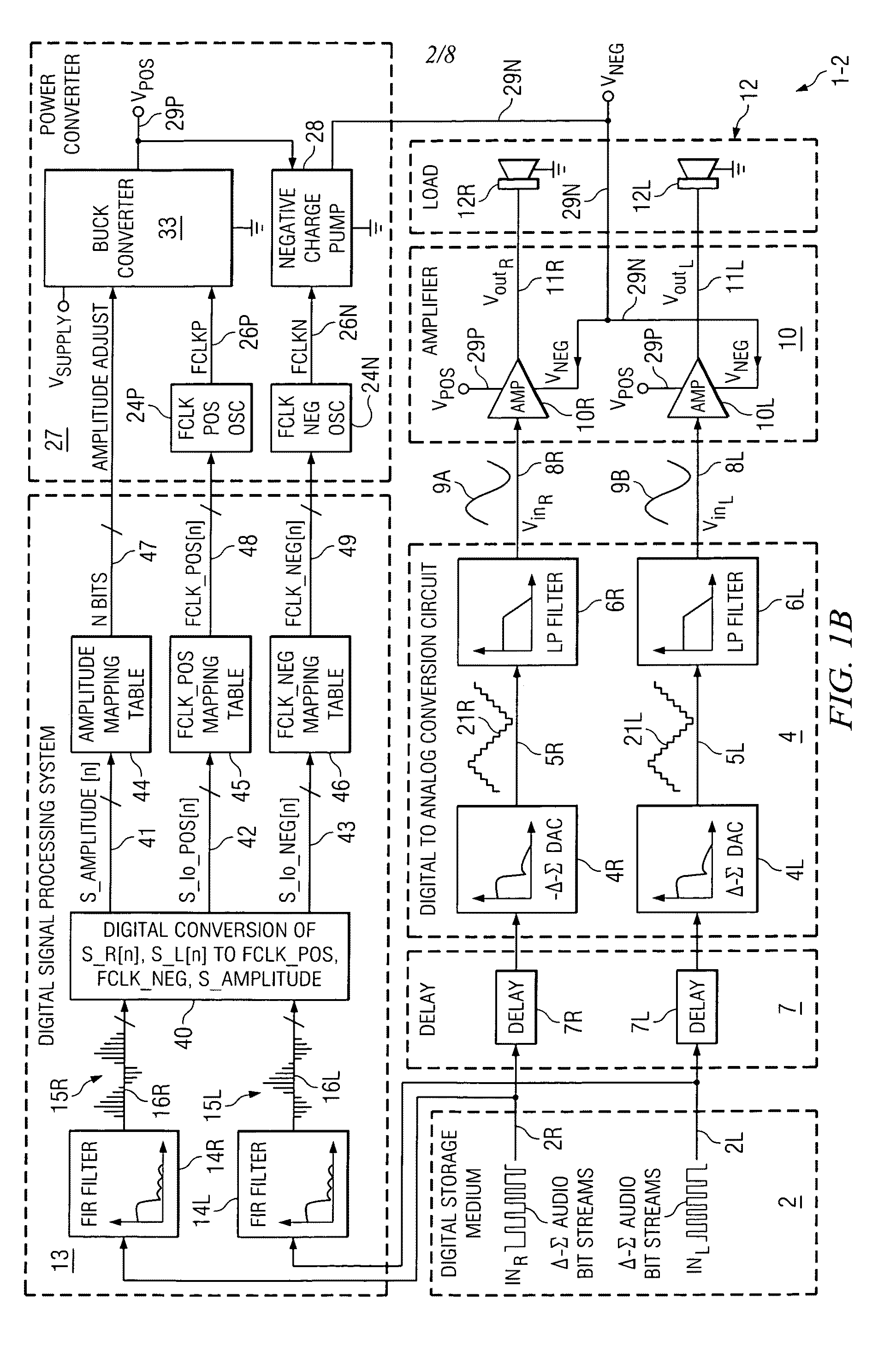
The present invention provides a technique for controlling power converters to supply power to an amplifier in a way that is energy-efficient during times when the amplifier does not require its peak current or voltage. This is achieved by detecting the signal amplitude information in the incoming digital data and converting it to a control signal to adjust the maximum available supply current of the amplifier. The invention also addresses distortion in the output signal caused by signal-dependent ripple and droop in the supply voltage. The invention provides a digital amplifying system that reduces power consumption during times when the load does not require the full power of the amplifier.

Problems solved by technology

However, in most cases the power requirements of the amplifier load vary greatly over time.
This makes the power converter less power-efficient because it dissipates more power than necessary for a significant portion of the amplifier operating time.
If the power converter switching frequency and the amplitude of its output voltage are not chosen for the worst case load condition, then the power converter circuitry may not be able to provide the power required by the amplifier during the signal-dependent peak load demand condition.
This results in an undesirable signal-dependent voltage “droop” in the amplifier supply voltage provided by the power converter.
This may degrade the performance of the amplifier that drives the load, for example by causing distortion in the output of an audio amplifier powered by the power converter.
However, this class G feedback approach suffers from a feedback lag whereby the supply voltages provided to the amplifier do not respond / settle fast enough to minimize distortion in the amplification, resulting in undesirable distortion of the output signal produced by the amplifier.
Specifically, since the amplifier's supply voltage also must have been adjusted and must have settled prior to the arrival of the amplifier's input signal, delay that occurs during any such feedback technique to adjust the amplifier supply voltage can produce undesirable effects, especially such as causing distortion in the amplifier's output signal.
However, in these prior art techniques there is always a delay of the feed-forward information.
As mentioned above, this also results in undesirable distortion of the output signal produced by the amplifier.

Method used


Image

  • Adaptive signal-feed-forward circuit and method for reducing amplifier power without signal distortion
  • Adaptive signal-feed-forward circuit and method for reducing amplifier power without signal distortion
  • Adaptive signal-feed-forward circuit and method for reducing amplifier power without signal distortion

Examples


Embodiment Construction

[0034]The present invention increases the power efficiency of an amplifier and a power conversion circuit, such as a charge pump or switching regulator for biasing the amplifier, wherein the amplifier supplies varying amounts of signal-dependent output current to a load. The load typically is fixed, i.e., time-independent. For example, the power efficiency of the charge pump or the switching regulator (or the like), together with the amplifier, can be varied by adjusting the switching frequency of the power converter, and optionally by also varying the output voltage of the power converter, according to the voltage and current demands of the amplifier and load. In accordance with the present invention, the adjustment of the switching frequency is accomplished by “looking ahead” at incoming digital data before it is converted to an analog signal and applied to the input of the amplifier. As an example, it might be known in advance, by digitally analyzing the incoming digital data, th...


PUM


Abstract

Digital amplifying circuitry delays a digital data signal (INR) to produce an output signal (VoutR). The delayed digital data signal is converted to an analog signal (VinR) for amplifying by an amplifier (10R). Signal amplitude information (S_R[n]) contained in the incoming digital data signal is detected during the delaying. The signal amplitude information is converted to a first control signal (S_Io_NEG[n]) in response to which an adjustable maximum available supply current of the amplifier is produced of least sufficient magnitude to avoid distortion during the amplifying to produce the output signal. The signal amplitude information also is converted to a second control signal (S_AMPLITUDE[n]) in response to which a supply voltage (VNEG) of the amplifier is controlled.

Description

BACKGROUND OF THE INVENTION[0001]The present invention relates generally to amplifier circuitry powered by power converter circuits, such as charge pumps and DC-DC converters, and more particularly to improvements which improve the power consumption efficiency of the amplifiers and associated power converter circuits in accordance with the amount of input-signal-dependent load power required from the amplifier and / or power converter circuit.[0002]When a DC-DC converter, such as a charge pump or switching regulator, is used to provide power to an amplifier, the conventional approach is to use a fixed switching frequency and an output voltage amplitude that are determined by the peak power requirement of the worst case load condition. However, in most cases the power requirements of the amplifier load vary greatly over time. For example, the volume settings and dynamic range of music signals output by an audio amplifier to speakers or headphones may have large variations over time. Th...

Claims


Application Information

Patent Timeline
Patent Type & Authority Patents(United States)
IPC IPC(8): H03F3/04
CPCH03F1/0244H03F1/0261H03F1/3223H03F3/3022H03F3/68H03F2200/03H03F2203/30015
Inventor WITMER, STEVEN B.KHUON, LUNALKULLBERG, BRIAN K.
Owner TEXAS INSTR INC
Learn More