Systems and methods for providing distributed load monopole antenna systems

a technology of distributed load monopoly and antenna system, applied in the field of antennas, can solve the problems of low efficiency of such systems, affecting the operation of antennas, and affecting the operation of antennas, and achieve the effect of enhancing curren

Inactive Publication Date: 2010-08-24
BOARD OF GOVERNORS FOR HIGHER EDUCATION STATE OF RHODE ISLAND & PROVIDENCE PLANTATIONS
View PDF25 Cites 97 Cited by
  • Summary
  • Abstract
  • Description
  • Claims
  • Application Information

AI Technical Summary

Benefits of technology

[0009]The invention provides a distributed load monopole antenna system that includes a monopole antenna including a radiation resistance unit, a current enhancing unit, and a conductive mid-section. In accordance with an embodiment, the radiation resistance unit is coupled to a transmitter base and the radiation resistance unit includes a radiation resistance unit base that is coupled to ground. The radiation resistance unit also includes a plurality of windings of an electrically conductive material wherein each winding includes an elongated portion that is substantially parallel with an elongated central axis of the monopole antenna. The elongated portions are positioned at a plurality of angularly disposed locations around the elongated central axis of the monopole antenna. The current enhancing unit is for enhancing current through the radiation resistance unit, and the conductive mid-section is intermediate the radiation resistance unit and the current enhancing unit.
[0010]In accordance with another embodiment, the radiation resistance unit is coupled to ground via a first plurality of selectively actuatable switches, and is coupled to a signal conductor via a second plurality of selectively actuatable switches such that both the first and second plurality of switches may be actuated to change an effective number of windings of the radiation resistance unit.
[0011]In accordance with a further embodiment, the radiation resistance unit includes a plurality of switches that may be selectively activated to change an effective number of windings of the radiation resistance unit, and the system further includes a wireless receiver coupled to an antenna analyzer for selectively activating the plurality of switches to change the effective number of windings of the radiation resistance unit responsive to signals received by the wireless receiver.

Problems solved by technology

Such tuning, however, is typically available only over a small range.
The efficiency of such systems, however, is generally low and radiation performance of such antennas will vary widely over the full tuning range of the antenna.
Either way, it becomes a significant problem at higher power levels to control the antenna matching and maintain efficiency.
Telescoping mast antennas present problems in achieving the lowest and highest frequency of operation as the necessary steps for adjusting the antenna are time consuming and labor intensive.

Method used


Image

  • Systems and methods for providing distributed load monopole antenna systems
  • Systems and methods for providing distributed load monopole antenna systems
  • Systems and methods for providing distributed load monopole antenna systems

Examples


Embodiment Construction

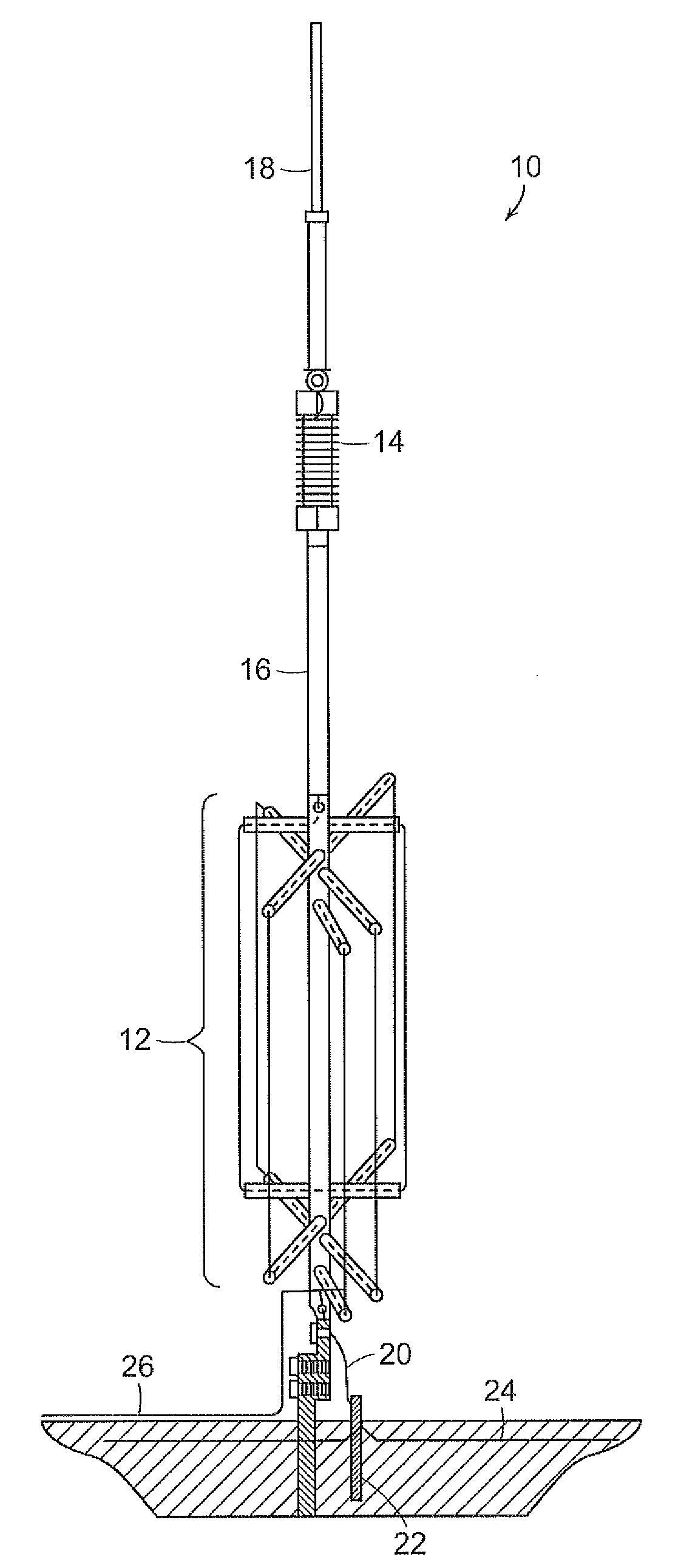
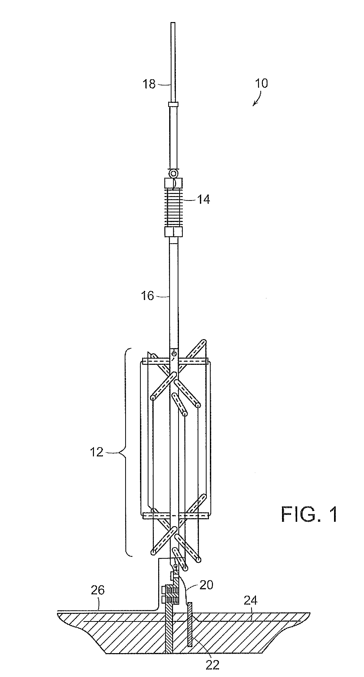
[0023]A distributed loaded monopole antenna may include a radiation resistance unit for providing significant radiation resistance, and a current enhancing unit for enhancing the current through the radiation enhancing unit as disclosed, for example in U.S. Pat. No. 7,187,335, the disclosure of which is hereby incorporated by reference. The radiation resistance unit may include a coil in the shape of a helix, and the current enhancing unit may include load coil and / or a top unit formed as a coil or hub and spoke arrangement. The radiation resistance unit is positioned between the current enhancing unit and a base (e.g., ground), and may, for example, be separated from the current enhancing unit by a distance of 2.5316×10⁻²λ where λ is the operating frequency of the antenna, to provide a desired current distribution over the length of the antenna.

[0024]As shown in FIG. 1, a diagrammatic view of an antenna system 10 of the invention includes a radiation resistance unit 12 and a curren...


PUM


Abstract

A distributed load monopole antenna system is disclosed that includes a monopole antenna including a radiation resistance unit, a current enhancing unit, and a conductive mid-section. The radiation resistance unit is coupled to a transmitter base and the radiation resistance unit includes a radiation resistance unit base that is coupled to ground. The radiation resistance unit also includes a plurality of windings of an electrically conductive material wherein each winding includes an elongated portion that is substantially parallel with an elongated central axis of the monopole antenna. The elongated portions are positioned at a plurality of angularly disposed locations around the elongated central axis of the monopole antenna. The current enhancing unit is for enhancing current through the radiation resistance unit, and the conductive mid-section is intermediate the radiation resistance unit and the current enhancing unit.

Description

PRIORITY[0001]The present application claims priority to U.S. Provisional Patent Application Ser. No. 60 / 786,437 filed Mar. 28, 2006.BACKGROUND[0002]The present invention generally relates to antennas, and relates in particular to antenna systems that include one or more monopole antennas.[0003]Monopole antennas typically include a single pole that may include additional elements with the pole, including for example, additional monopole antennas. Non-monopole antennas generally include antenna structures that form two or three dimensional shapes such as diamonds, squares, circles etc.[0004]As wireless communication systems (such as wireless telephones and wireless networks) become more ubiquitous, the need for smaller and more efficient antennas such as monopole antennas (both large and small) increases. Many monopole antennas operate at very low efficiency yet provide satisfactory results. In order to meet the demand for smaller and more efficient antennas, the efficiency of such a...

Claims


Application Information

Patent Timeline
Patent Type & Authority Patents(United States)
IPC IPC(8): H01Q9/32
CPCH01Q9/32
Inventor VINCENT, ROBERT J.
Owner BOARD OF GOVERNORS FOR HIGHER EDUCATION STATE OF RHODE ISLAND & PROVIDENCE PLANTATIONS
Why Eureka
Try Eureka