
Coating of Mn+1AXn material for electrical contact elements

a technology of mn+1axn and material, applied in the direction of non-rotary current collectors, coupling device connections, natural mineral layered products, etc., can solve the problems of material production methods, etc., and achieve the effects of low friction coefficient, low friction coefficient, and limited lifetim

Inactive Publication Date: 2010-08-31
ABB RES LTD +1
View PDF5 Cites 11 Cited by
  • Summary
  • Abstract
  • Description
  • Claims
  • Application Information

AI Technical Summary

Benefits of technology

"The present invention provides an electric contact element with a low friction contact layer that overcomes the problems associated with previous layers. The contact layer is made of a multielement material that includes a nanocomposite of M-X nanocrystals and amorphous regions with M, A, X elements in one or several phases. The nanocomposite has good mechanical, chemical, temperature, and contact properties, and it also exhibits ductile behavior and shock resistance. The composition of the compounds in the nanocomposite is similar to the composition of the M-X phases. The multielement material can be deposited at low temperatures using various deposition processes. The invention also provides a method for making a coating with the widest possible range of properties compared to other materials."

Problems solved by technology

A problem with the described multielement material is that methods to produce the material are carried out at high temperatures (700-1400° C.).
This means that an electrical electric contact element, which has a body made of a material that is not shape resistant at high temperatures, for instance copper or aluminum cannot be made use of.

Method used


Image

  • Coating of M<sub>n+1</sub>AX<sub>n </sub>material for electrical contact elements
  • Coating of M<sub>n+1</sub>AX<sub>n </sub>material for electrical contact elements
  • Coating of M<sub>n+1</sub>AX<sub>n </sub>material for electrical contact elements

Examples


Embodiment Construction

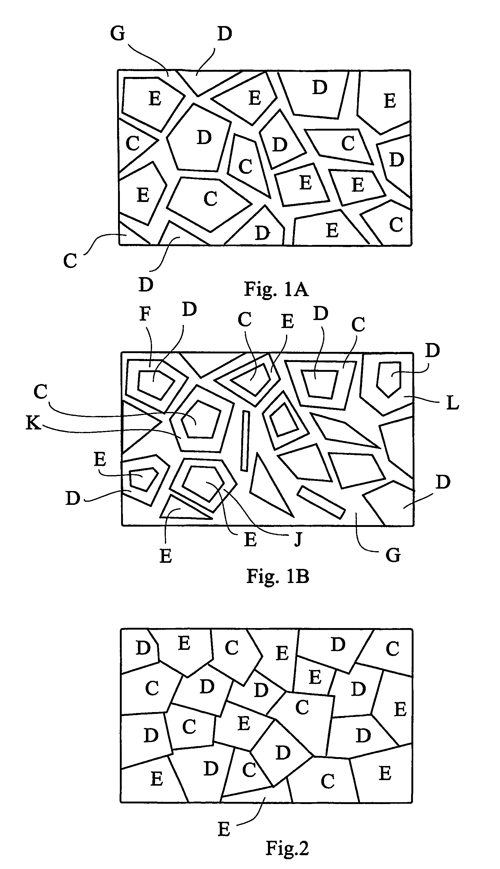
[0066]FIG. 1A depicts a structure of a multielement material layer with equal or similar composition as any of a layered carbide and nitride that can be described as Mn+1AXn where M is a transition metal or a combination of a transition metals, n is 1, 2, 3 or higher, A is an group A element or a combination of a group A element, and X is Carbon, Nitrogen or both, comprising a nanocomposite of M-X, M-A-X nanocrystals and amorphous regions with M, A, X elements in one or several phases, such as M-A, A-X, M-A-X, X. The multielement material has amorphous regions (denoted G in the figure) mixed with regions in of the multielement material in a nanocrystalline state (denoted C, D, E in the figure). The individual regions (denoted C, D and E in the picture) in the structure is a single element, binary phases, ternary phases and / or higher order phases depending on the number of atomic elements in the film.

[0067]FIG. 1B depicts a structure of a multielement material with the elements that ...


PUM

PropertyMeasurementUnit
thicknessaaaaaaaaaa
thicknessaaaaaaaaaa
thicknessaaaaaaaaaa

Abstract

An element for making an electric contact to a contact member for enabling an electric current to flow between the element and the contact member. The element includes a body having at least a contact surface thereof coated with a contact layer applied against the contact member. The contact layer includes a film including a multielement material with equal or similar composition as any of a layered carbide or nitride that can be described as Mn+1AXn, where M is a transition metal or a combination of a transition metals, n is 1, 2, 3 or higher, A is an group A element or a combination of a group A element, element and X is Carbon, Nitrogen or both.

Description

CROSS-REFERENCE TO RELATED APPLICATIONS[0001]This application claims priority to U.S. provisional patent applications 60 / 511,424 and 60 / 511,430 filed 16 Oct. 2003 and is the national phase under 35 U.S.C. §371 of PCT / IB2004 / 003390 filed 18 Oct. 2004.TECHNICAL FIELD[0002]An element for making an electric contact to a contact member for enabling an electric current to flow between said element and said contact member. The element comprising a body having at least a contact surface thereof coated with a contact layer to be applied against said contact member. The contact layer comprises a continuous or discontinuous film comprising a multielement material.BACKGROUND ART[0003]Recent studies has shown that compounds having the general formula Mn+1AXn exhibit unusual and exceptional mechanical properties as well as advantageous electrical thermal and chemical properties. Despite having high stiffness these compounds are readily machinable, resistant to thermal shock, unusually damage tole...

Claims


Application Information

Patent Timeline
Patent Type & Authority Patents(United States)
IPC IPC(8): H01H1/02C23C30/00H01RH01R13/03H01R39/20H01R41/00
CPCH01H1/02H01R13/03H01R13/035H01R13/26Y10T428/31678
Inventor ISBERG, PETEREKLUND, PEREMMERLICH, JENSHULTMAN, LARSHOGBERG, HANSLJUNGCRANTZ, HENRIK
Owner ABB RES LTD
Learn More