
Method for operating a frequency converter of a generator

a frequency converter and generator technology, applied in the direction of electric generator control, process and machine control, instruments, etc., can solve the problems of critical and limited grid voltage drop, and increase the output current of the converter in the event of grid voltage drop, so as to reduce the grid voltage and reduce the output voltage of the dc link circuit

Inactive Publication Date: 2010-08-31
GENERAL ELECTRIC CO
View PDF8 Cites 10 Cited by
  • Summary
  • Abstract
  • Description
  • Claims
  • Application Information

AI Technical Summary

Benefits of technology

"The invention provides a method for increasing the output current of a frequency converter in a wind energy turbine in the event of a significant drop in grid voltage. This is achieved by reducing the output voltage of the DC link circuit and / or the operation frequency of the electronic switches of the DC / AC converter. The method can be implemented simultaneously by reducing both the output voltage and the operating frequency of the frequency converter. The reducing step is initiated when the grid voltage decreases for a short time and is terminated when the normal grid voltage increases again. The technical effect is to increase the current flow through the electronic switches without increasing energy losses, thus improving the efficiency of the frequency converter."

Problems solved by technology

However, due to thermal stresses applied to the electronic components of the frequency converter of a generator converting mechanical energy into electrical energy, increasing the output current of the converter in the event of a grid voltage drop is critical and limited.

Method used


Image

  • Method for operating a frequency converter of a generator
  • Method for operating a frequency converter of a generator
  • Method for operating a frequency converter of a generator

Examples


Embodiment Construction

[0016]Reference will now be made in detail to the various embodiments of the invention, one or more examples of which are illustrated in the drawings. Each example is provided by way of explanation of the invention, and is not meant as a limitation of the invention. For example, features illustrated or described as part of one embodiment can be used on or in conjunction with other embodiments to yield yet a further embodiment. It is intended that the present invention includes such modifications and variations.

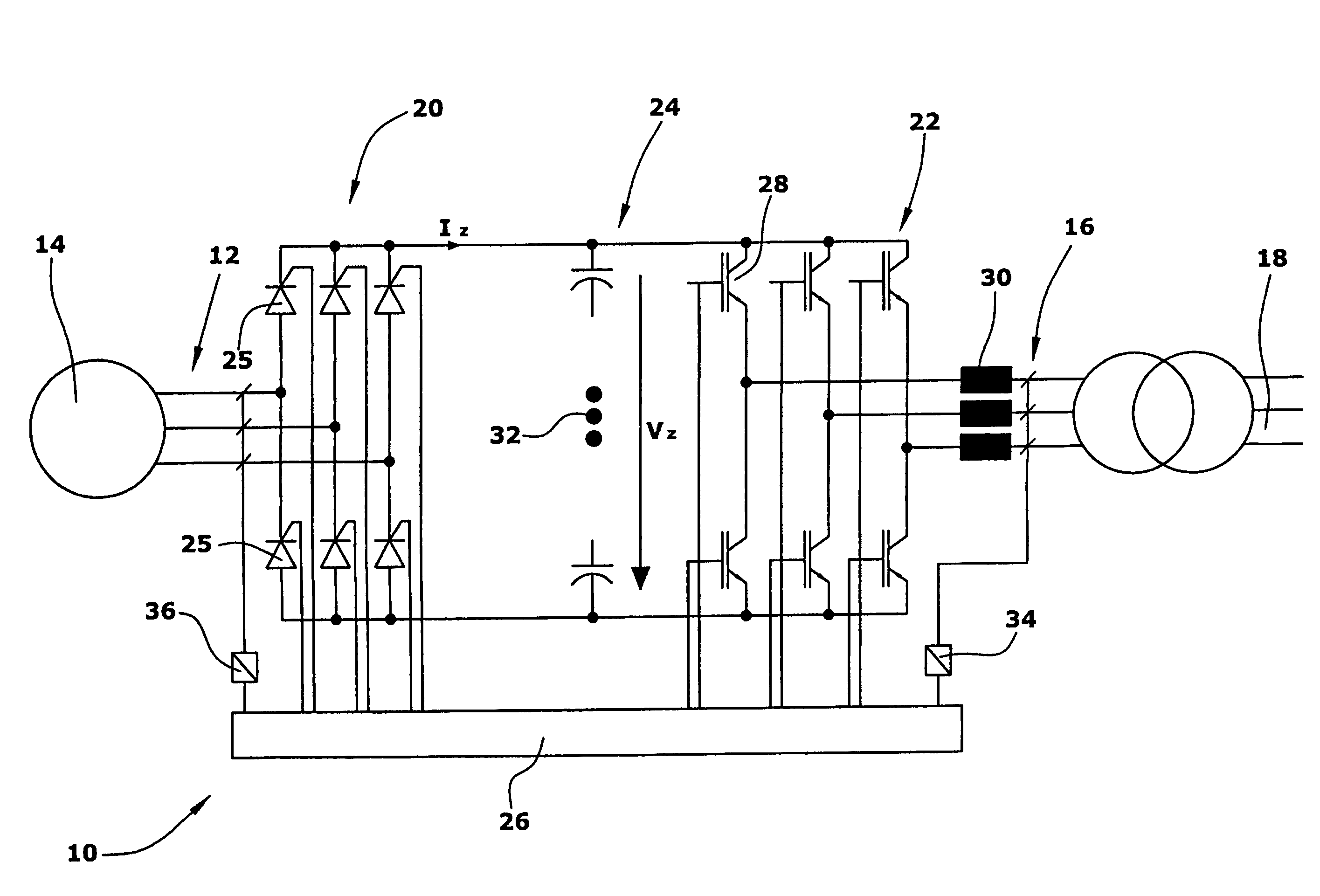
[0017]In the drawing, the circuitry of a frequency converter 10 as used for providing electrical power to a power grid is shown. The frequency converter is arranged between the output 12 of a generator 14 of a wind energy turbine (not shown) and the input 16 of a power grid 18.

[0018]The frequency converter 10 includes three major stages, namely an input stage, an intermediate stage, and an output stage. The input stage is configured as an AC / DC converter 20, while the output s...


PUM


Abstract

The method relates to the operation of a frequency converter of a generator in particular of a wind energy turbine, in the event of a substantial grid voltage drop, wherein the frequency converter (10) comprises an AC / DC converter (20), to be connected to the generator (14), a DC / AC converter (22) to be connected to the voltage grid (18), and a DC link circuit (24) for connecting the AC / DC converter (20) to the DC / AC converter (22). The method comprises the step of reducing an output voltage of the DC link circuit (24) for increasing an output current of the DC / AC converter (22) and / or reducing the operation frequency of electronic switches (28) of the DC / AC converter (22) for increasing the output current of the DC / AC converter (22).

Description

BACKGROUND OF THE INVENTION[0001]1. Field of the Invention[0002]The present invention relates to the operation of power converters for supplying electrical power to a grid and, in particular, to a frequency converter of a generator of a wind energy turbine.[0003]2. Related Prior Art[0004]Electrical power in public power grids is supplied by diverse energy sources converting mechanical energy into electrical energy. The main energy sources supporting public power grids are coal power plants and nuclear power plants. Several other types of energy sources, in particular power plants of regenerative energy like solar power plants, water power plants or wind energy turbines, also contribute to support the public power grid.[0005]In the past, in the event of a significant grid voltage drop in a public power grid, it was required that in such an event wind energy turbines are shut down automatically. However, due to the increased number of wind energy turbines it becomes more and more impo...

Claims


Application Information

Patent Timeline
Patent Type & Authority Patents(United States)
IPC IPC(8): H02M5/458H02M5/45H02J3/38
CPCH02M5/4585H02J3/383H02J3/386H02M2001/0048Y02B70/1491Y02E10/563Y02E10/763H02J2300/28H02J2300/24H02J3/381Y02B70/10Y02E10/56Y02E10/76H02J3/46H02M1/0048
Inventor JANSSEN, WILHELMMENKE, DETLEF
Owner GENERAL ELECTRIC CO
Learn More